High-performance shell-and-tube heat exchanger

A shell-and-tube heat exchanger, high-performance technology, applied in heat exchanger types, heat exchanger shells, indirect heat exchangers, etc., can solve the problems of long heat exchange time, inability to achieve efficient heat exchange, etc. Reasonable and easy to use effect

Pending Publication Date: 2022-02-18
江苏埃米诺装备制造有限公司
View PDF0 Cites 0 Cited by
  • Summary
  • Abstract
  • Description
  • Claims
  • Application Information

AI Technical Summary

Problems solved by technology

[0002] Traditional shell-and-tube heat exchangers are usually installed with several circular heat exchange plates in the shell to exchange heat between cold and hot media. This form of heat exchange takes a long time and cannot achieve efficient heat exchange. Therefore still need to improve

Method used


Image

  • High-performance shell-and-tube heat exchanger
  • High-performance shell-and-tube heat exchanger

Examples


Embodiment Construction

[0012] All features disclosed in this specification, or steps in all methods or processes disclosed, may be combined in any manner, except for mutually exclusive features and / or steps.

[0013] Any feature in this specification, unless specifically stated, can be replaced by other equivalent or alternative features with similar purpose. That is, unless expressly stated otherwise, each feature is one example only of a series of equivalent or similar features.

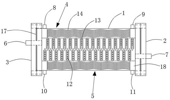
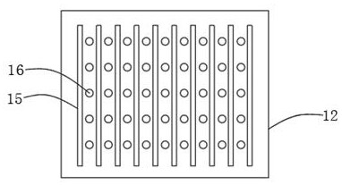
[0014] Such as figure 1 , 2 The high-performance shell-and-tube heat exchanger shown includes a shell 1, the front end of the shell 1 is provided with a front splint 3, and the rear end of the shell 1 is provided with a rear splint 2, and the front splint 1 is A cooling medium inlet 6 is provided on the top, a cooling medium outlet 7 is provided on the rear splint 2, a first heating medium inlet 8 and a second heating medium outlet 9 are provided on the upper side of the housing 1, and the housing 1 A second heat medi...


PUM


Abstract

Disclosed is a high-performance shell-and-tube heat exchanger comprising a shell, a front clamping plate is arranged at the front end of the shell, a rear clamping plate is arranged at the rear end of the shell, a cold medium inlet is formed in the front clamping plate, and a cold medium outlet is formed in the rear clamping plate; the heat exchanger is reasonable in structural design and convenient to use, and cold and hot media can be simply, conveniently and efficiently subjected to heat exchange.

Description

technical field [0001] The invention relates to the field of heat exchangers, in particular to a high-performance shell-and-tube heat exchanger. Background technique [0002] Traditional shell-and-tube heat exchangers are usually installed with several circular heat exchange plates in the shell to exchange heat between cold and hot media. This form of heat exchange takes a long time and cannot achieve efficient heat exchange. Therefore still need to improve. Contents of the invention [0003] In order to solve the above-mentioned problems, the present invention provides a high-performance shell-and-tube heat exchanger, including a shell, the front end of the shell is provided with a front splint, and the rear end of the shell is provided with a rear splint , the front splint is provided with a cooling medium inlet, the rear splint is provided with a cooling medium outlet, the upper side of the housing is provided with a first heating medium inlet and a second heating medi...

Claims


Application Information

Patent Timeline
IPC IPC(8): F28D7/00F28F9/00F28F9/24
CPCF28D7/0066F28F9/001F28F9/24F28F9/005
Inventor 庞澄龙
Owner 江苏埃米诺装备制造有限公司
Why Eureka
Try Eureka