
Double-cavity visible gastrointestinal tube and double-cavity injection device with same

A technology of gastrointestinal tubes and intestinal tubes, applied in catheters, rectal mirrors, rectal electron microscopes, etc., can solve the problems of inconvenient administration, easy insertion into tissues, and troublesome treatment, so as to achieve smooth and reliable treatment and prevent tube blockage , the effect of convenient tube placement

Pending Publication Date: 2022-04-05
PEKING UNIV SHENZHEN HOSPITAL
View PDF15 Cites 0 Cited by
  • Summary
  • Abstract
  • Description
  • Claims
  • Application Information

AI Technical Summary

Problems solved by technology

Most of the gastrointestinal tubes in the related art are a flexible tube with openings in the corresponding area of ​​the stomach and the corresponding area of ​​the intestinal tract. The gastrointestinal tube of this structure is not convenient for the separate drug administration of the stomach and intestinal tract.
In addition, the gastrointestinal tube is a straight tube. When it is inserted into the field cavity, its lower end is easy to embed into the tissue, resulting in tube blockage, and the tube blockage has caused great trouble to subsequent treatment, and even requires re-insertion of the tube.
In addition, in the intuitive process, it is difficult to intuitively obtain the state of the intestinal tract, and it is not convenient to place the tube

Method used


Image

  • Double-cavity visible gastrointestinal tube and double-cavity injection device with same
  • Double-cavity visible gastrointestinal tube and double-cavity injection device with same
  • Double-cavity visible gastrointestinal tube and double-cavity injection device with same

Examples


Embodiment Construction

[0051] Embodiments of the present invention are described in detail below, examples of which are shown in the drawings, wherein the same or similar reference numerals designate the same or similar elements or elements having the same or similar functions throughout. The embodiments described below by referring to the accompanying drawings are exemplary and are intended to explain the present invention, but cannot be construed as limitations to the present invention. Based on the embodiments in the present invention, those skilled in the art do not make creative work premise All other embodiments obtained below all belong to the protection scope of the present invention.

[0052] In describing the present invention, it should be understood that the terms "center", "longitudinal", "transverse", "length", "width", "thickness", "upper", "lower", "front", " Back", "Left", "Right", "Vertical", "Horizontal", "Top", "Bottom", "Inner", "Outer", "Clockwise", "Counterclockwise", "Axial",...


PUM


Abstract

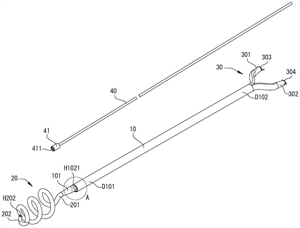
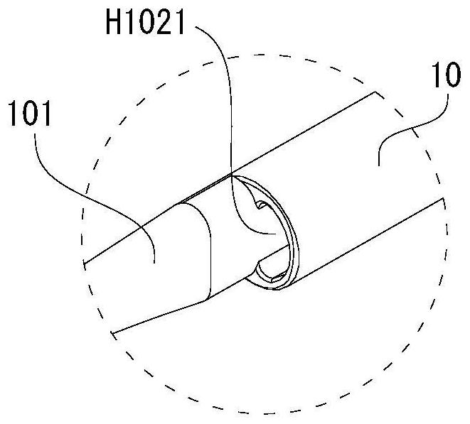
The double-cavity visible gastrointestinal tube comprises a main tube, an intestinal tube, a guide wire and a camera, the main tube is provided with a near end, a far end, a nasogastric channel and a nasointestinal channel, the nasogastric channel and the nasointestinal channel penetrate from the far end to the near end, and the near end is provided with a first liquid outlet communicated with the nasogastric channel and an interface part communicated with the nasointestinal channel. The intestinal tube is of an elastic spiral structure and is provided with a connecting end and a liquid outlet end, the connecting end is connected with the connector part, and the liquid outlet end is provided with a second liquid outlet through which liquid flows out; one end of the guide wire sequentially penetrates through the nasointestinal channel and the intestinal canal and then penetrates out of the second liquid outlet, and the other end of the guide wire is located outside the far end. The camera is arranged at one end of the guide wire, and the other end of the guide wire is provided with a data connector in signal connection with the camera. According to the double-cavity visible gastrointestinal tube provided by the invention, medicine can be fed through the nasogastric channel and the nasointestinal channel respectively, and one tube can meet different requirements during treatment. In addition, the problem of blockage of the accommodating tube in the enteric cavity is effectively prevented.

Description

technical field [0001] The invention relates to a medical gastrointestinal tube, in particular to a double-cavity visible gastrointestinal tube and a double-cavity injection device with it. Background technique [0002] Gastrointestinal tube is a medical tube suitable for transgastric nutrition supply and gastrointestinal decompression. Most of the gastrointestinal tubes in the related art are a flexible tube with openings in the area corresponding to the stomach and the area corresponding to the intestinal tract. The gastrointestinal tube with this structure is not convenient for separate drug administration in the stomach and intestinal tract. In addition, the gastrointestinal tube is a straight tube. When it is inserted into the field cavity, its lower end is easy to embed into the tissue, resulting in tube blockage, and the tube blockage has caused great trouble to subsequent treatment, and even requires re-insertion of the tube. In addition, during the intuitive proces...

Claims


Application Information

Patent Timeline
IPC IPC(8): A61J15/00A61M25/00A61B1/04A61B1/31A61M31/00
Inventor 周海君
Owner PEKING UNIV SHENZHEN HOSPITAL
Learn More