Surface mounted inductor
A surface-mounted, inductor technology, applied in the direction of inductors, fixed inductors, transformers/inductor cores, etc., can solve the problems of wiring parts too close to winding parts, winding parts short-circuited, exposed, etc.
- Summary
- Abstract
- Description
- Claims
- Application Information
AI Technical Summary
Problems solved by technology
Method used
Image
Examples
no. 1 Embodiment approach
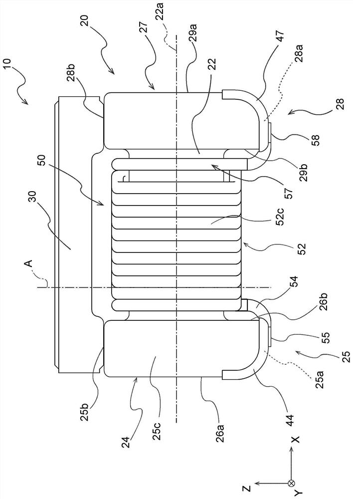
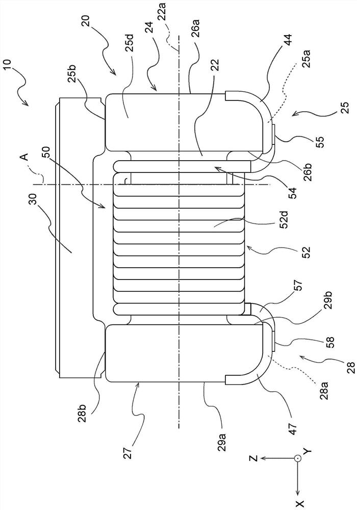
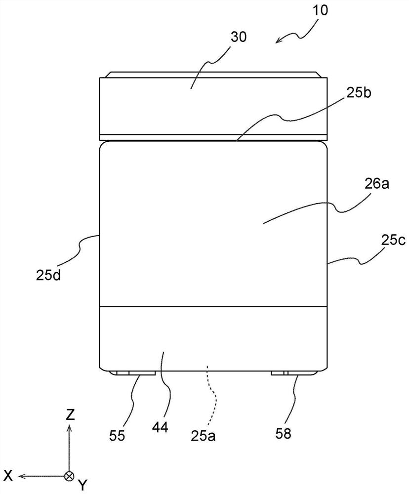
[0085] figure 1 It is a front view of a surface mount inductor 10 (hereinafter simply referred to as "inductor 10") according to an embodiment of the present invention. The inductor 10 has a core 20 as a drum core, a plate core 30 , electrode portions 44 , 47 and a winding 50 . The inductor 10 has a substantially rectangular parallelepiped outer shape, and is surface-mounted on a mounting substrate by, for example, being transported by sucking and holding the upper surface of the core 30 by a suction nozzle of a mounting machine. However, the inductor 10 is not limited to having the core 30 , and the suction nozzle may be adsorbed to other parts of the inductor 10 .
[0086] The core 20 and the board core 30 are bonded to each other with an adhesive such as an epoxy-based adhesive. Figure 9 is to remove figure 1 A cross-sectional view of a portion of core 30 in inductor 10 is shown. Such as Figure 9 As shown, the core 20 has a winding core portion 22 and a pair of flang...
no. 2 Embodiment approach
[0119] Figure 12 to Figure 17 It is a front view, a rear view, a left side view, a right side view, a top view, and a bottom view of the inductor 110 which concerns on 2nd Embodiment of this invention. The inductor 110 according to the second embodiment is the same as the inductor 10 according to the first embodiment except that the shape of the lower inner edge 125f of the flange portions 124 and 127 of the core 120 is different. About the inductor 110 which concerns on 2nd Embodiment, only the difference from the inductor 10 is demonstrated, and the description of the common point with the inductor 10 is abbreviate|omitted.
[0120] Such as Figure 12 As shown, the lower inner edge 125f of the flange portion 124 is chamfered (surface C). Like the inductor 110 , the lower inner edge 125 f of the flange portion 24 may be chamfered without R-processing. In this case, the R machining radius of the lower outer edge 25e is preferably larger than the chamfering dimension of the...
no. 3 Embodiment approach
[0123] Figure 18 It is a front view of the inductor 210 according to the third embodiment of the present invention, excluding the flat portion. In the inductor 210 according to the second embodiment, the first part side part 252c is inclined with respect to the virtual plane A perpendicular to the axial direction of the winding core part 22, and the first part upper side part 252b is parallel to the virtual plane A. Others are the same as the inductor 10 according to the first embodiment. Regarding the inductor 210 according to the third embodiment, only the points different from the inductor 10 will be described, and the description of the points common to the inductor 10 will be omitted.
[0124] Such as Figure 18 As shown, in the inductor 210, in the first part 252 of the winding 250, the first part side part 252c connecting the first part upper side part 252b and the first part lower side part 52a, with respect to the virtual plane A It is wound obliquely with an incl...
PUM
 Abstract
Description
Claims
Application Information
 - R&D Engineer
- R&D Manager
- IP Professional
- Industry Leading Data Capabilities
- Powerful AI technology
- Patent DNA Extraction
Browse by: Latest US Patents, China's latest patents, Technical Efficacy Thesaurus, Application Domain, Technology Topic, Popular Technical Reports.
© 2024 PatSnap. All rights reserved.Legal|Privacy policy|Modern Slavery Act Transparency Statement|Sitemap|About US| Contact US: help@patsnap.com


