
Rotating electrical machine

A technology of rotating electrical machines and rotating axes, which is applied in the direction of electric components, electrical components, electromechanical devices, etc., and can solve problems such as the performance degradation of rotating electrical machines and the reduction in the number of turns of coil wires

Inactive Publication Date: 2016-01-27
AISIN SEIKI KK
View PDF5 Cites 2 Cited by
  • Summary
  • Abstract
  • Description
  • Claims
  • Application Information

AI Technical Summary

Problems solved by technology

As a strategy against this problem, increasing the thickness of the insulation can be considered; however, if the thickness of the insulation is simply increased, the number of turns of the coil wire will be reduced, and the performance of the rotating electrical machine will be degraded

Method used


Image

  • Rotating electrical machine
  • Rotating electrical machine
  • Rotating electrical machine

Examples


Embodiment Construction

[0030] Embodiments of the present invention are described below with reference to the drawings.

[0031] basic configuration

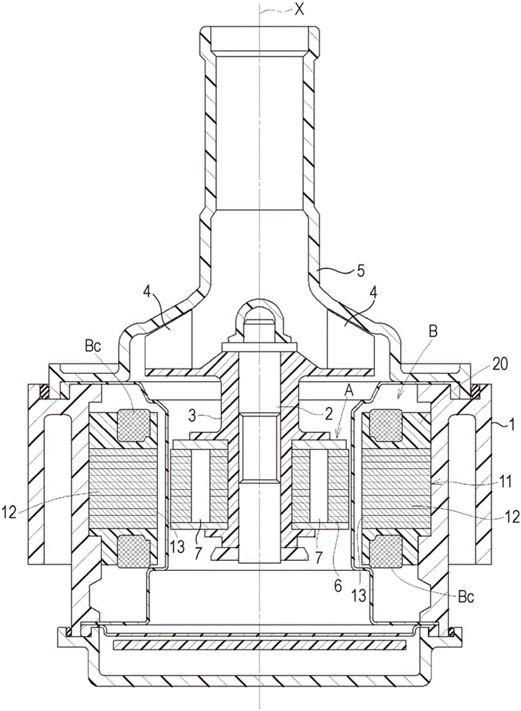
[0032] Such as figure 1 As shown in , a brushless motor as a rotating electrical machine is configured to include: a support shaft 2 whose both ends are supported in a casing 1 coaxially with the rotation axis X; rotatable on the outer surface; a rotor A that rotates integrally with the rotating shaft 3; and a stator B that is disposed in an area surrounding the rotor A.

[0033] The rotary shaft 3 is made of resin, and a pusher 4 is integrally formed at the end of the rotary shaft 3 . This electric motor is used in a water pump that circulates coolant around an inverter or circulates coolant between an engine and a radiator in a passenger car or the like in a state where a propeller 4 of the electric motor is accommodated in a water pump housing 5 middle.

[0034] A brushless motor is taken as an example of the rotary electric machine; however,...


PUM


Abstract

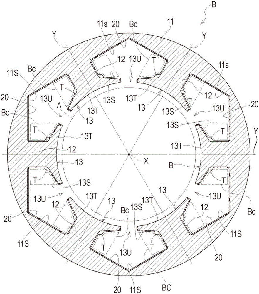
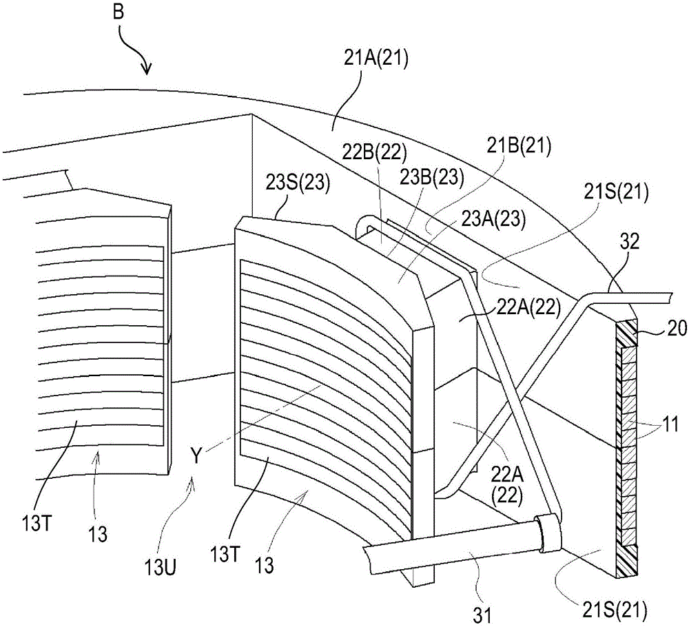
A rotating electrical machine includes: a core including an annular yoke portion (11) disposed while being centered around a rotation axis (X); toothed portions (12) protruding from the yoke portion in a radial direction; and a tooth flange portion (13) circumferentially sticking out from a protruding end of each of the toothed portions while being centered around the rotation axis; and an insulator (20) covering a region from the toothed portion to the tooth flange portion, wherein the insulator includes a tooth cover portion (22), and a flange cover portion (23), and a reinforced portion (T) is formed at the boundary between the tooth cover portion and the flange cover portion, and includes a first restricting surface (Ra), and a second restricting surface (Rb).

Description

technical field [0001] The present invention relates to a rotating electric machine, and more particularly, to a technique of winding a coil wire around a plurality of teeth. Background technique [0002] In the rotating electric machine disclosed in JP2008-92700A (Correction Document 1) having the above-mentioned configuration, the stator is configured such that a plurality of teeth are formed on the inner periphery of the annular stator core, an insulating part is provided covering the teeth, and surrounding A coil wire is wound around the tooth-shaped portion on which the insulating portion is provided. In the rotating electric machine disclosed in Patent Document 1, in the protruding end portion of the tooth-shaped portion, a flange portion is formed so as to extend in the circumferential direction, and the inner surface of the stator core, the outer surface of the tooth-shaped portion, and the A coil slot is formed in a region surrounded by the flange portion of the to...

Claims


Application Information

Patent Timeline
Patent Type & Authority Applications(China)
IPC IPC(8): H02K3/34H02K3/28H02K1/14H02K1/27
CPCH02K3/325H02K2203/12H02K3/522H02K3/48H02K3/487H02K3/34H02K3/345H02K3/52
Inventor 小川博臣服部修二坂仓真也
Owner AISIN SEIKI KK
Learn More