
Motor rotating speed measuring device

A technology for measuring device and motor speed, applied in the direction of measuring device, linear/angular velocity measurement, velocity/acceleration/shock measurement, etc.

Pending Publication Date: 2022-05-13
东莞市点精科技有限公司
View PDF0 Cites 0 Cited by
  • Summary
  • Abstract
  • Description
  • Claims
  • Application Information

AI Technical Summary

Problems solved by technology

[0003] However, the existing measurement methods all need to define a specific measurement direction, which has great limitations on the use of measurement devices

Method used


Image

  • Motor rotating speed measuring device
  • Motor rotating speed measuring device
  • Motor rotating speed measuring device

Examples


Embodiment Construction

[0018] Embodiments of the present invention are described in detail below, examples of which are shown in the drawings, wherein the same or similar reference numerals designate the same or similar elements or elements having the same or similar functions throughout. The embodiments described below by referring to the figures are exemplary and are intended to explain the present invention and should not be construed as limiting the present invention.

[0019] The present invention will be further described in detail below through specific embodiments in conjunction with the accompanying drawings.

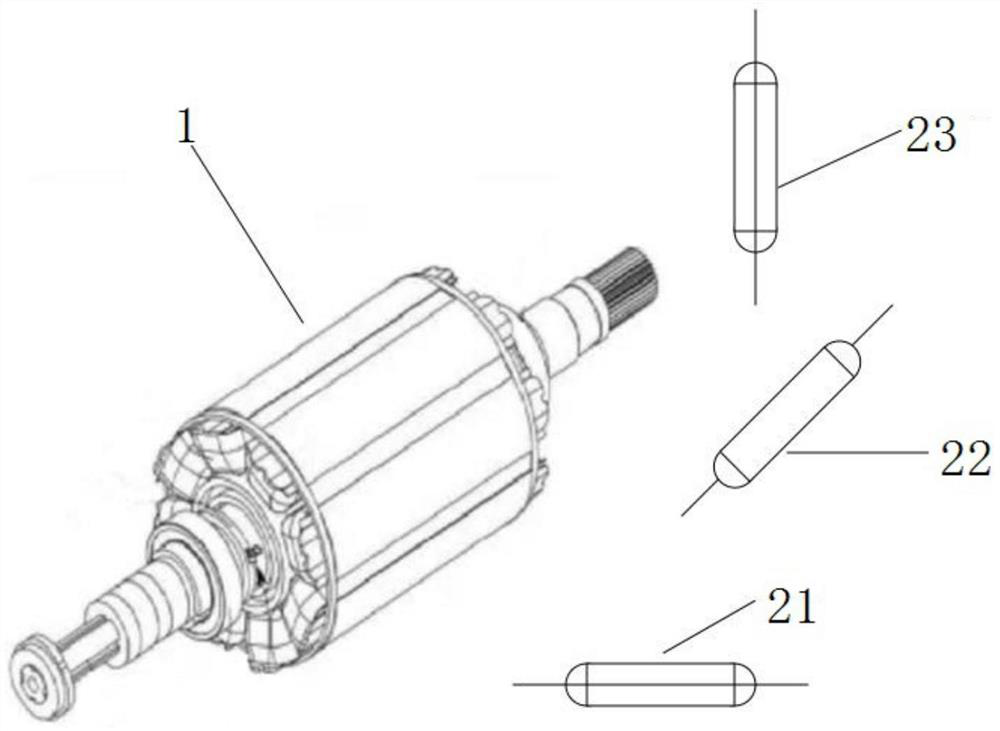
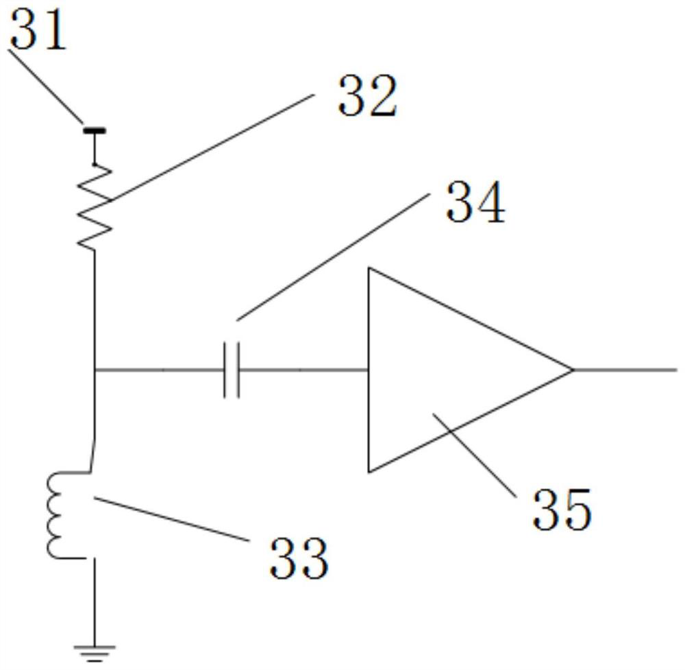
[0020] like Figure 2~Figure 3 As shown, the present invention provides a motor speed measuring device to solve the technical problems raised in the background art above.

[0021] The invention provides a motor speed measuring device, comprising:

[0022] The signal detector is used to collect the state signal of the motor 1;

[0023] The controller is connected to the signal dete...


PUM


Abstract

The invention provides a motor rotating speed measuring device comprising a signal detector used for collecting a motor state signal; the controller is connected with the signal detector and is used for calculating the motor state according to the motor state signal acquired by the signal detector; the signal detector comprises a first signal detector arranged along the X axis, a second signal detector arranged along the Y axis and a third signal detector arranged along the Z axis. A plurality of signal detectors are arranged in the X-axis direction, the Y-axis direction and the Z-axis direction to point to different directions, measurement can be carried out in any direction, a magnetic field in any direction can be measured, the signal detector on the side detects a motor state signal, the waveform of the signal and the rotating phase of the motor are synchronous, the rotating speed of the motor can be calculated according to the frequency of the waveform, and the measurement accuracy is improved. The rotating speed of the motor can be effectively measured.

Description

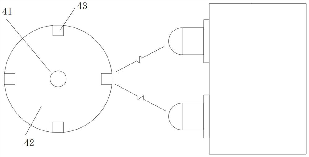
technical field [0001] Embodiments of the present invention relate to the technical field of motor detection, and in particular, to a device for measuring the rotational speed of a motor. Background technique [0002] In various motor applications and manufacturing occasions, it is necessary to measure the speed of the motor. The traditional methods include photoelectric method, stroboscopic light source reflection observation method and so on. The principle of the photoelectric method is to use a pair of luminescent tubes and photosensitive receiving tubes to count the received reflective signals against a certain reflective mark 43 provided on the turntable 42 above the rotating motor 41, and then the motor can be measured. Rotational speed, this method must have an optical mark linked to the rotating part of the motor, and the measuring device must illuminate the observation mark in a small range of directions (see figure 1 ). Another method that is slightly more compli...

Claims


Application Information

Patent Timeline
Patent Type & Authority Applications(China)
IPC IPC(8): G01P3/481
CPCG01P3/481
Inventor 雷卫军
Owner 东莞市点精科技有限公司
Learn More