
Punching device for computer keyboard base

A computer keyboard and punching device technology, applied in metal processing, etc., can solve the problems of low processing efficiency, automatic processing of debris grooves, inconvenient disassembly of punching plates and electric push rods, etc., to achieve the effect of convenient material collection

Pending Publication Date: 2022-05-27
苏州凌瑞电子有限公司
View PDF0 Cites 0 Cited by
  • Summary
  • Abstract
  • Description
  • Claims
  • Application Information

AI Technical Summary

Problems solved by technology

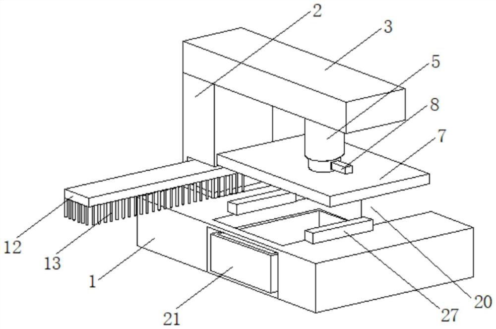
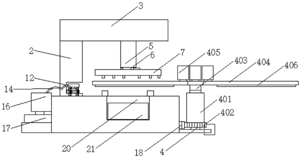
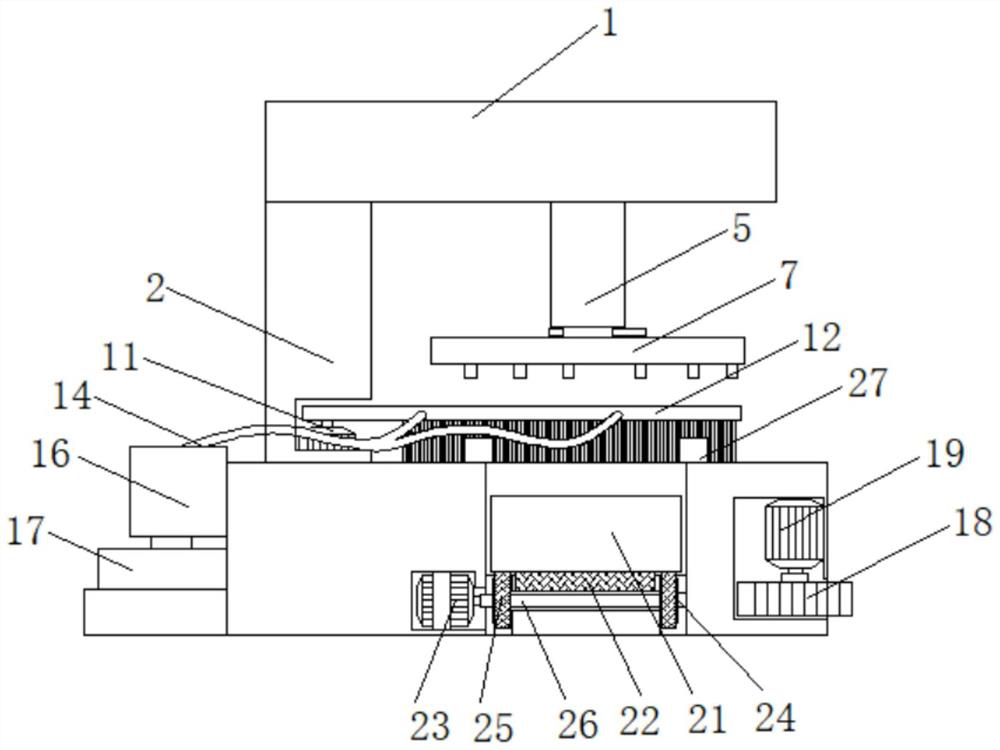
[0004] The purpose of the present invention is to solve the problems that the punching of the base requires manual assistance, the processing efficiency is low, the debris tank cannot be processed automatically when the debris tank is full, the punching plate and the electric push rod are not easy to disassemble, and the problems of the debris falling on the workbench are provided. A punching device for a computer keyboard base to solve the problems raised in the above-mentioned background technology

Method used


Image

  • Punching device for computer keyboard base
  • Punching device for computer keyboard base
  • Punching device for computer keyboard base

Examples


Embodiment Construction

[0030] In order to make the technical means, creative features, achievement goals and effects realized by the present invention easy to understand, the present invention will be further described below with reference to the specific embodiments.

[0031] In the description of the present invention, it should be noted that the terms "upper", "lower", "inner", "outer", "front end", "rear end", "two ends", "one end" and "the other end" The orientation or positional relationship indicated by etc. is based on the orientation or positional relationship shown in the accompanying drawings, and is only for the convenience of describing the present invention and simplifying the description, rather than indicating or implying that the indicated device or element must have a specific orientation, with a specific orientation. The orientation configuration and operation are therefore not to be construed as limiting the invention. Furthermore, the terms "first" and "second" are used for desc...


PUM


Abstract

The punching device for the computer keyboard base comprises a workbench, a supporting seat is arranged at the top end of the workbench, a feeding structure is arranged on the right side of the workbench, a collecting groove is formed in the inner side of the workbench, and a positioning block is arranged at the position, located on the right side of the supporting seat, of the top end of the workbench. A second motor is mounted in the workbench, and a mounting plate is arranged at the top end of the supporting seat. By arranging an air cylinder, a fixing plate, an air suction plate and a gear ring, a second motor drives the air cylinder to rotate through a gear, the air cylinder rotates to drive the fixing plate and a keyboard base to rotate to the position above a positioning block, at the moment, an air pump at the top end of the fixing plate is controlled to stop running, and air pressure in the fixing plate and the air suction plate disappears; when the keyboard base is punched, the base is separated from the air suction plate and falls on the positioning block, the electric push rod can operate to drive the punching plate to move downwards to punch the keyboard base, and the problem that manual assistance is needed for base punching, and the machining efficiency is low is effectively solved.

Description

technical field [0001] The invention relates to the technical field of computer keyboard base processing, in particular to a punching device for a computer keyboard base. Background technique [0002] The computer keyboard is a channel for inputting the control information of text information into the computer. It evolved from the keyboard of the English typewriter. When it first appeared on the computer, it was still a component called "teletypewriter". , it is necessary to punch holes on the computer keyboard mold, so as to facilitate the installation of keys in the later stage. [0003] After the computer keyboard base is punched, the punched base needs to be removed, and then a new base needs to be placed. This process requires workers to wait on one side for execution, which makes the processing automation of the base low, and the current punching device There is a debris slot for collecting the falling punching debris, but when the debris slot is full, the staff canno...

Claims


Application Information

Patent Timeline
Patent Type & Authority Applications(China)
IPC IPC(8): B26D7/01B26D7/06B26D7/18B26D7/32B26F1/14
CPCB26F1/14B26D7/01B26D7/06B26D7/32B26D7/1863B26D7/18B26D2007/208Y02P70/10
Inventor 凃瑞麟武献松
Owner 苏州凌瑞电子有限公司
Learn More