Method and device for monitoring and identifying fatigue state of driver

A driver fatigue and recognition method technology, applied in the field of driver fatigue state monitoring and recognition method and its device, can solve problems such as large computing power requirements and complex algorithms

Pending Publication Date: 2022-07-08
浙江天圆智控科技有限公司
View PDF0 Cites 0 Cited by
  • Summary
  • Abstract
  • Description
  • Claims
  • Application Information

AI Technical Summary

Problems solved by technology

[0004] The purpose of the present invention is to overcome the existing defects, provide a driver fatigue state monitoring and identification method and its device, and solve the problem that the current algorithm for judging driver fatigue state is complex and requires a large computing power

Method used


Image

  • Method and device for monitoring and identifying fatigue state of driver
  • Method and device for monitoring and identifying fatigue state of driver
  • Method and device for monitoring and identifying fatigue state of driver

Examples


Embodiment 1

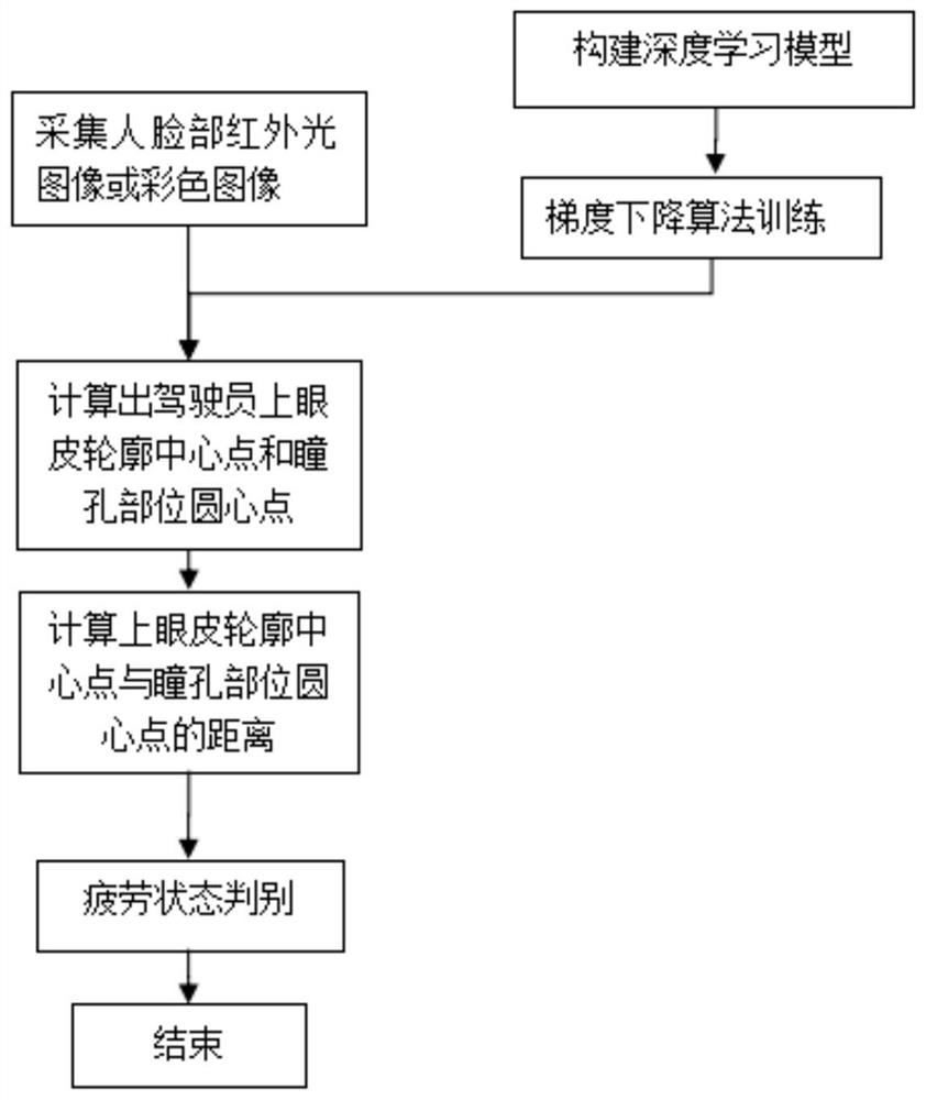
[0064] A round of steps S1 to S4 is performed for the first time:

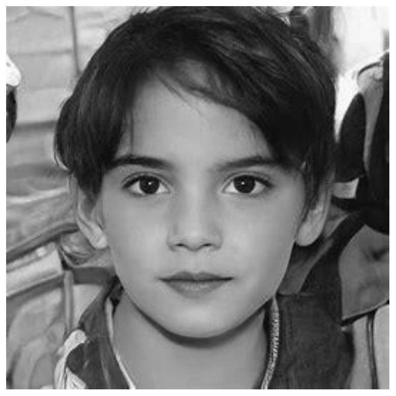
[0065] Get an image of the driver's face such as Figure 5 (actually in color, due to the format requirements, it is adjusted to black and white, and the actual picture is shown in the substantive examination reference materials submitted at the same time);

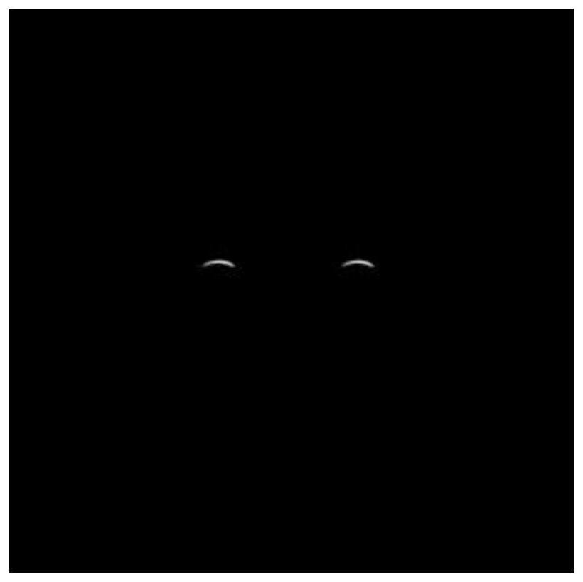
[0066] A lightweight deep learning model is used to infer the driver's face image, and at the same time, the model diagram of the driver's upper eyelid contour and the model diagram of the pupil part are obtained, such as Image 6 and Figure 7 shown;

[0067] After obtaining the position and shape of the upper eyelid contour in the model diagram, add a rectangular frame to its outer side, and calculate the center points of the rectangular frame. These center points are regarded as the center points of the upper eyelid contour of the driver, such as Figure 8 In the same way, the center point of the pupil of the driver is obtained, such as Figure 9 s...

Embodiment 2

[0076] The first execution remains unchanged, and the average distance d1 in the time period t1 is obtained. The difference between this embodiment and Embodiment 1 is:

[0077] Execute steps S1 to S4 once again:

[0078] Get an image of the driver's face such as Figure 15 (actually in color, due to the format requirements, it is adjusted to black and white, and the actual picture is shown in the substantive examination reference materials submitted at the same time);

[0079] A lightweight deep learning model is used to infer the driver's face image, and at the same time, the model diagram of the driver's upper eyelid contour and the model diagram of the pupil part are obtained, such as Figure 16 and 17 shown;

[0080] After obtaining the position and shape of the upper eyelid contour in the model diagram, add a rectangular frame to its outer side, and calculate the center points of the rectangular frame. These center points are regarded as the center points of the upper...


PUM


Abstract

The invention provides a driver fatigue state monitoring and identifying method, which comprises the following steps of: acquiring a face image of a driver in real time, reasoning to obtain a model diagram of an upper eyelid contour and a pupil part of the driver, and calculating a central point of the upper eyelid contour and a circle center point of the pupil part of the driver; and calculating the distance between the center point of the eyelid contour and the circle center point of the pupil part of the driver, and judging whether the driver is in a fatigue state or not by analyzing the change of the distance. The invention also provides a device for monitoring and identifying the fatigue state of the driver. According to the method and the device for monitoring and identifying the fatigue state of the driver, a lightweight deep learning model is designed, the model is adopted to calculate the distance from the center point of the eyelid contour on the eyes of the driver to the circle center point of the pupil part, and the fatigue state is monitored in real time according to the change of the distance; the fatigue state of the driver is accurately judged, and meanwhile the requirement for hardware and computing power is not high.

Description

technical field [0001] The invention relates to a monitoring method and device, in particular to a monitoring and identification method and device for driver fatigue state. Background technique [0002] With the continuous improvement of the number of motor vehicles and the continuous growth of the number of drivers, road traffic safety has become one of the key factors of economic and social development. According to the statistics of the World Health Organization, more than 1.2 million people die in traffic accidents every year, and millions of people are injured or disabled due to traffic accidents. Fatigue driving of drivers is one of the most important factors leading to accidents. [0003] In recent years, in order to reduce traffic accidents caused by fatigued driving, various methods have been adopted to detect the driver's fatigue state and issue warnings. At present, the mechanism research on fatigue monitoring is relatively mature. The method based on the combina...

Claims


Application Information

Patent Timeline
IPC IPC(8): G06V20/59G06V40/18G06V10/82G06V10/774G06K9/62G06N3/08
CPCG06N3/08G06F18/214
Inventor 熊天运陈春雷
Owner 浙江天圆智控科技有限公司
Why Eureka
Try Eureka