Cinerary casket storage rack capable of placing photos
A technology for urns and storage racks, which is applied in the direction of building types, buildings, monuments, etc. It can solve the problems of not having the function of placing photos, and it is difficult to find urns, and achieve the effect of avoiding wear and tear
- Summary
- Abstract
- Description
- Claims
- Application Information
AI Technical Summary
Problems solved by technology
Method used
Image

Examples
Embodiment 1
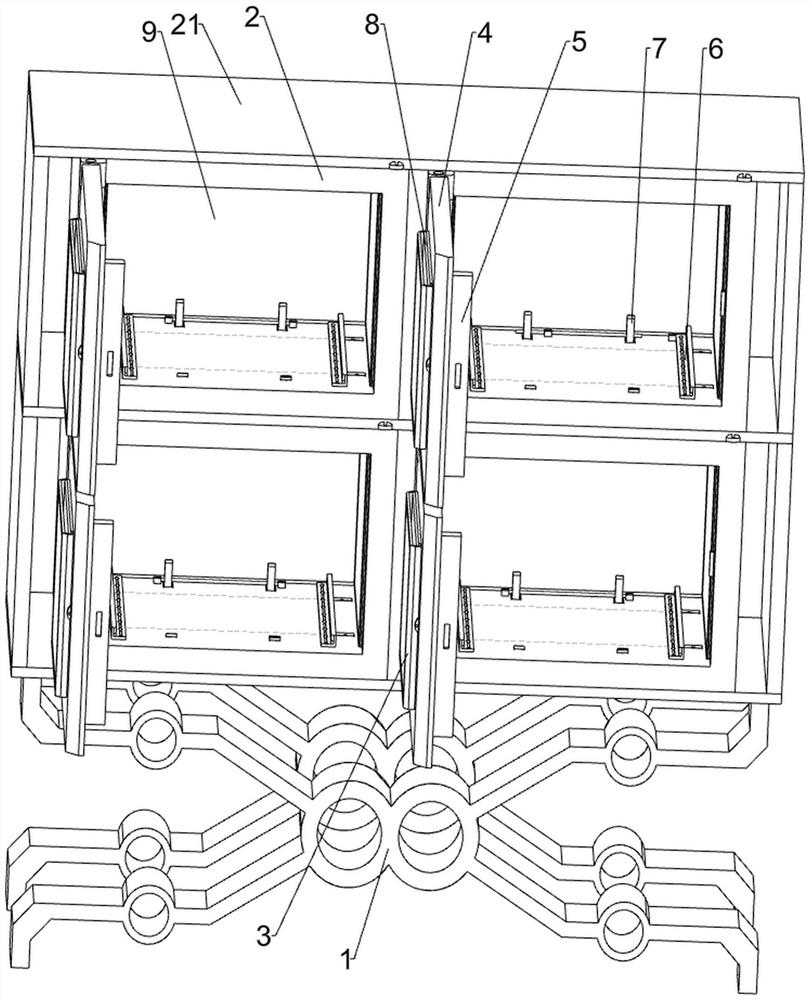
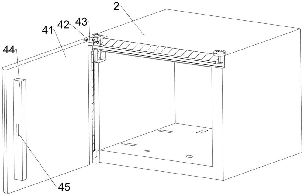
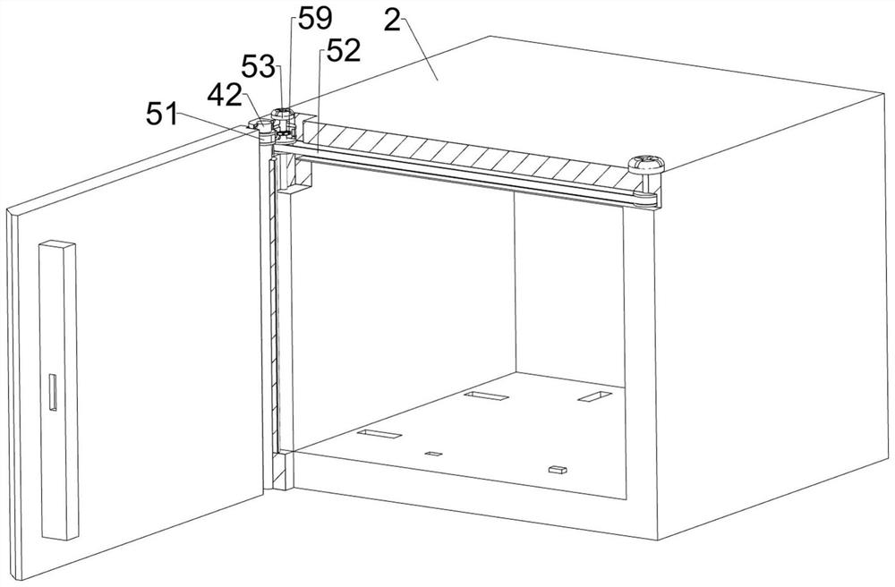
[0036] An urn storage rack that can place photos, including a support frame 1, a mounting frame 2, a fixing frame 21, a transparent placing frame 3, an opening and closing mechanism 4 and a locking mechanism 5, please refer to Figure 1-Figure 6 As shown in the figure, the outer bottom of the fixed frame 21 is symmetrically installed with the support frame 1 through bolt connection, and four installation frames 2 are installed on the inner side of the fixed frame 21 evenly spaced. The operator can put the urn into the installation frame 2 for storage. , an opening and closing mechanism 4 is installed on the front side of the installation frame 2. When the opening and closing mechanism 4 swings back and resets, the opening and closing mechanism 4 can realize the sealing of the installation frame 2, and four transparent placing frames are fixed on the opening and closing mechanism 4. 3. The operator can put the photo into the transparent placing frame 3. The installation frame 2 ...
Embodiment 2
[0043] On the basis of Embodiment 1, a limit mechanism 6 is also included. The limit mechanism 6 includes a guide rod 61, a slider 62, a second spring 63, a limit plate 64, an auxiliary roller 65 and a short rod 66. Please refer to figure 1 , Figure 7 and Figure 8 As shown in the figure, the left and right sides of the inner bottom of the installation frame 2 are symmetrically embedded in the front and rear, and a guide rod 61 is embedded and fixed. The guide rod 61 is slidably sleeved with a slider 62. There is a second spring 63, the second spring 63 is sleeved on the guide rod 61, and a limit plate 64 is installed between the tops of the two sliders 62 on the left and the tops of the two sliders 62 on the right by bolting. When the operator places the urn between the two limit plates 64, the limit plate 64 can limit the urn, and eight short rods 66 are connected to the bottom of the limit plate 64 with evenly spaced embedded rotation. An assisting roller 65 is installed...
Embodiment 3
[0048] On the basis of Embodiment 1 and Embodiment 2, a placing mechanism 8 is also included. The placing mechanism 8 includes a placing plate 81, a rotating rod 82, a column gear 83, a rack 84 and a rotating wheel 85. Please refer to figure 1 , Figure 11 , Figure 12 and Figure 13As shown, a placing plate 81 is slidably placed in the transparent placing frame 3. When the placing plate 81 moves upwards, the placing plate 81 can realize the upward movement of the photo. The rack 84, the middle of the left side of the cover plate 41 is connected with a rotating rod 82 in a front-to-back symmetrical manner, and the outer sides of the rotating rods 82 on the front and rear sides are fixedly sleeved with a runner 85. When the operator pushes the runner 85 to rotate, the runner 85 The rotating rod 82 can be driven to rotate. The inner side of the rotating rod 82 on both sides of the front and rear is fixedly sleeved with a column gear 83. The column gear 83 meshes with the rack ...
PUM
 Abstract
Description
Claims
Application Information
 - R&D
- Intellectual Property
- Life Sciences
- Materials
- Tech Scout
- Unparalleled Data Quality
- Higher Quality Content
- 60% Fewer Hallucinations
Browse by: Latest US Patents, China's latest patents, Technical Efficacy Thesaurus, Application Domain, Technology Topic, Popular Technical Reports.
© 2025 PatSnap. All rights reserved.Legal|Privacy policy|Modern Slavery Act Transparency Statement|Sitemap|About US| Contact US: help@patsnap.com