Pressure regulating appts.

A technology of pressure regulating device and pressure fluid, which is applied in the direction of valve device, transportation and packaging, fluid pressure control, etc. It can solve the problems of life reduction, easy displacement, and high pressure regulation accuracy, etc., and achieve the improvement of pressure regulation accuracy , improved life, stable and correct opening and closing action

Inactive Publication Date: 2004-12-01
SMC CORP
View PDF1 Cites 4 Cited by
  • Summary
  • Abstract
  • Description
  • Claims
  • Application Information

AI Technical Summary

Problems solved by technology

[0003] In such a pressure regulating device, the above-mentioned diaphragm is easily displaced not only in the direction of the axis, but also in the direction of inclination of the axis. Due to this property, the poppet valve mounted on the diaphragm is prone to inclination. The opening and closing action of the poppet ...

Method used


Image

  • Pressure regulating appts.
  • Pressure regulating appts.
  • Pressure regulating appts.

Examples


Embodiment Construction

[0024] Several preferred embodiments of the pressure regulating device of the present invention will be described in detail below with reference to the accompanying drawings.

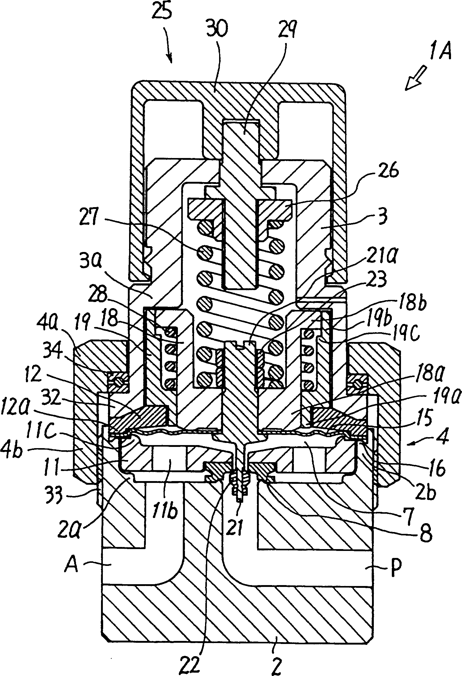
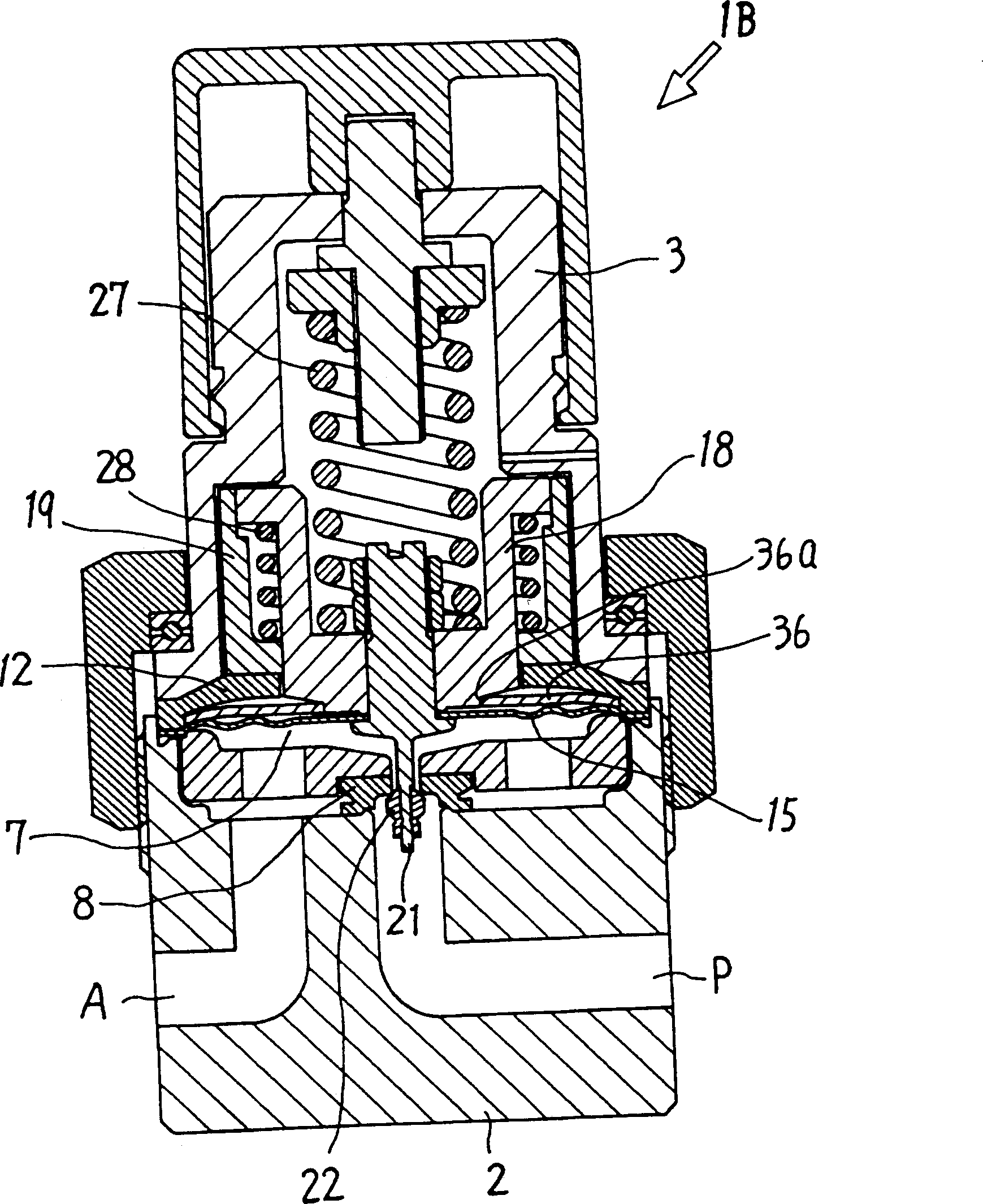
[0025] figure 1 and figure 2 The first embodiment of the present invention is shown. The pressure regulating device 1A of the first embodiment includes a short cylindrical body 2, a cylindrical cover 3 joined to the upper surface of the body 2, and these bodies are freely detachably joined. 2 and the nut-shaped fastening ring 4 of the housing 3.

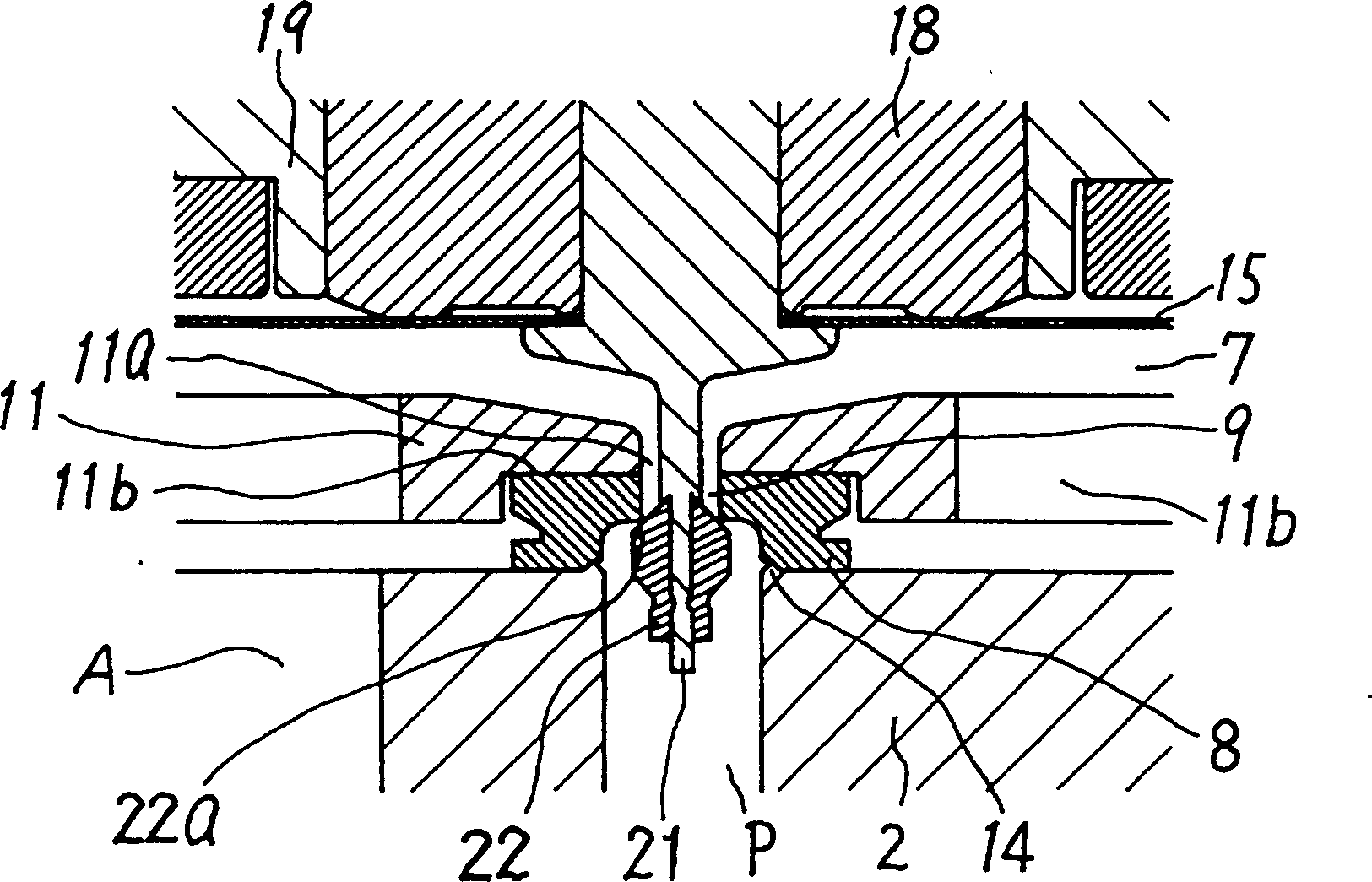
[0026] An input hole P for introducing pressure fluid and an output hole A for outputting pressure-regulated pressure fluid are arranged on the side of the above-mentioned body 2, and a pressure chamber 7 opened by these holes P and A is arranged on the top of the body 2. . A valve seat 8 is installed in the pressure chamber 7 at a position where the inlet port P opens, and a valve seat hole 9 in the center of the valve seat 8 communicates with the inlet p...


PUM


Abstract

The opening and closing operations of a poppet valve are stabilized by preventing a diaphragm and the poppet valve from being inclined so that the pressure adjusting accuracy of a regulator is increased. For that purpose, the diaphragm is fitted with a piston and the poppet valve for opening and closing a valve seat and the piston is guided for moving in the axial direction with a sleeve by slidably inserting the piston into the sleeve.

Description

technical field [0001] The present invention relates to a pressure regulating device for regulating the pressure of pressurized fluid such as compressed air. Background technique [0002] Such a pressure regulating device introduces pressurized fluid from an input port, adjusts its pressure to a set value, and then outputs it from an output port. An example thereof is disclosed in US Pat. No. 5,458,001. The pressure regulating device has a valve seat provided in the flow path connecting the input hole and the output hole, a diaphragm freely displaceably provided on the secondary side of the valve seat, connected to the diaphragm and capable of passing through the diaphragm. The displacement of the poppet valve opens and closes the above-mentioned valve seat from the primary side, and the pressure regulating spring applies elastic force to the above-mentioned diaphragm in the direction of opening the valve seat of the poppet valve. The poppet valve opens and closes the valve...

Claims


Application Information

Patent Timeline
IPC IPC(8): G01L7/08F16K7/00G05D16/02G05D16/06
CPCG05D16/0661Y10T137/7825F16K7/00
Inventor 宫添真司胜田博行田岛正道
Owner SMC CORP
Why Eureka
Try Eureka