Supercharge Your Innovation With Domain-Expert AI Agents!

Fluorescent lamp

A technology of fluorescent lamps and glass tubes, applied in the field of fluorescent lamps

Inactive Publication Date: 2005-04-27
PANASONIC CORP
View PDF3 Cites 0 Cited by
  • Summary
  • Abstract
  • Description
  • Claims
  • Application Information

AI Technical Summary

Problems solved by technology

[0005] In order to solve these problems, the present invention aims to provide a fluorescent lamp which does not cause the spacer to come off even when the precision of the gap between the glass tubes is not high, and which is easy to install the spacer.

Method used


Image

  • Fluorescent lamp
  • Fluorescent lamp
  • Fluorescent lamp

Examples


Embodiment Construction

[0020] below with attached Figure 1 An example of an embodiment of the present invention will be described.

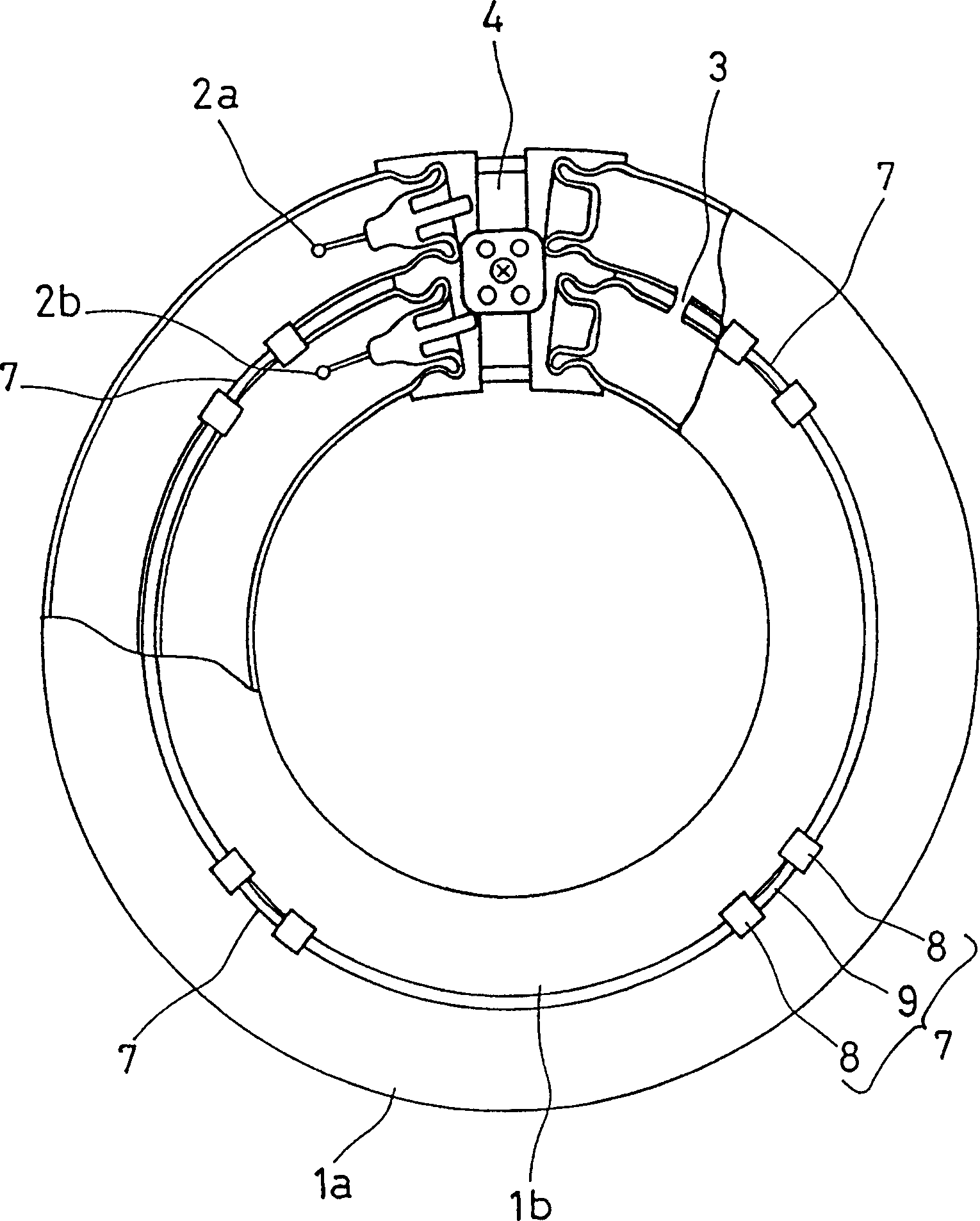
[0021] Such as figure 1 As shown, the fluorescent lamp of this embodiment is a double ring fluorescent lamp having glass tubes 1a, 1b of double rings of large and small sizes. Phosphor is coated on the inside of the glass tubes 1a, 1b. Electrode coils 2a, 2b are arranged at one end of the glass tubes 1a, 1b. The other ends of the glass tubes 1a, 1b are sealed, and a bridge 3 connecting the glass tubes 1a, 1b is provided near the sealing portion. Thus, two glass tubes 1a, 1b form one discharge circuit.

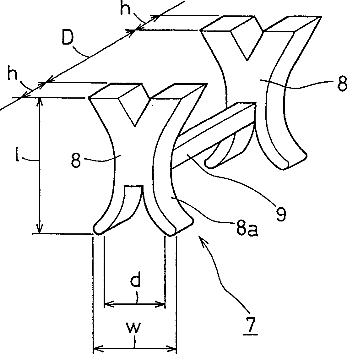
[0022] The glass tubes 1a, 1b are sealed with argon gas and mercury at a suitable pressure (several hundred Pa), and then the metal cap 4 is joined. Spacers 7 are provided at multiple positions in the gap between the glass tube 1a and the glass tube 1b.

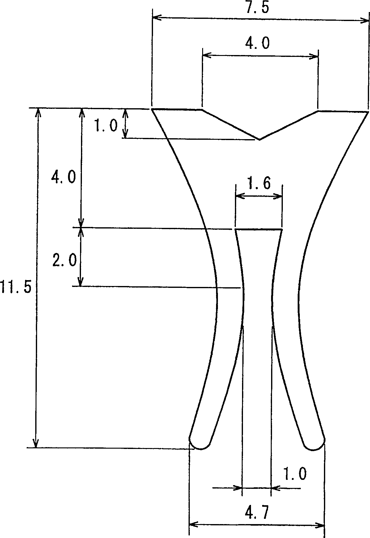
[0023] Such as figure 2 As shown, the spacer 7 is composed of a linear bridge 9 combined with two support t...


PUM


Abstract

The invention provides a fluorescent lamp, having high compression strength in its gap and high torsion strength by preventing falling off of a spacer when the gap precision of a glass tube is not sufficient in the fluorescent lamp where plural glass tubes are mutually coupled to form discharge paths. This is constituted so that the spacer 7 to be intervened in the gap of the coupled glass tubes 1a, 1b and plural support tongs 8 are coupled by a bridging body 9 along the shaft direction of the glass tube.

Description

technical field [0001] The present invention relates to a fluorescent lamp in which a discharge circuit is formed by connecting a plurality of glass tubes. Background technique [0002] Originally, fluorescent lamps having a discharge circuit connecting a plurality of glass tubes are generally known as so-called compact fluorescent lamps and spherical fluorescent lamps or double ring fluorescent lamps. The above-mentioned glass tubes are generally connected by bridging or molding. [0003] In bridging fluorescent lamps, when the lamp is attached to a lighting fixture, stress that shortens the gap between the connected glass tubes occurs, and in order to increase the lamp strength against this stress, for example, JP-A-62-264547, JP-A-5-76132, etc. discloses a structure in which spacers are provided in gaps between glass tubes. These spacers serve to supplement the lamp intensity when the gap precision of the glass tube is high. In order to prevent the spacer from falling ...

Claims


Application Information

Patent Timeline
Patent Type & Authority Patents(China)
IPC IPC(8): H01J61/32
CPCH01J61/322
Inventor 明星稔山内英树竹村勉北田昭雄
Owner PANASONIC CORP
Features
  • R&D
  • Intellectual Property
  • Life Sciences
  • Materials
  • Tech Scout
  • Unparalleled Data Quality
  • Higher Quality Content
  • 60% Fewer Hallucinations
Learn More