Multi optical function calculation holographic device and its manufacturing method
What is AI technical title?
AI technical title is built by PatSnap AI team. It summarizes the technical point description of the patent document.
An optical function and computational holography technology, applied in the field of computational holography, can solve the problems of high cost and small space bandwidth product, and achieve the effect of high efficiency and cost reduction
Inactive Publication Date: 2005-07-06
SHANGHAI INST OF OPTICS & FINE MECHANICS CHINESE ACAD OF SCI
View PDF0 Cites 0 Cited by
Summary
Abstract
Description
Claims
Application Information
AI Technical Summary
This helps you quickly interpret patents by identifying the three key elements:
Problems solved by technology
Method used
Benefits of technology
Problems solved by technology
However, its cost is high and its space bandwidth product is small, so its practical application is more restricted.
Method used
Image
Click on the blue label to locate the original text in one second.
Reading with bidirectional positioning of images and text.
Examples
Embodiment 1
[0049] Example 1: Fabrication of a computational holographic device capable of realizing two optical functions:
[0050] 1. Obtain the initial phase distribution according to the optimization algorithm 1 , 2 :
[0051]Using optimization algorithms (such as simulated annealing, direct binary search, etc.) to optimize the 100×100-pixel images shown in Figures 4a and 4b, the phase distribution 1 , 2 .
[0052] 2. Find the right Taber illuminator:
[0053] In this embodiment, M=2, and the corresponding compression ratio of the Taber illuminator is 2. According to the theoretical knowledge of the Talbot effect, it can be known that a phase plate with a phase value of 0 and -π / 2 can realize a checkerboard periodic illumination with a compression ratio of 2 at the 1 / 8 Talbot distance, as shown by the shaded and white parts in Figure 5 Show. Its phase distribution is shown in Figure 5.
[0054] 3. Yes 1 , 2 To recode: to 1 , 2 Re-encoding can be performed as ...
Embodiment 2
[0057] Embodiment 2: Fabrication of a computational holographic device capable of realizing 7 optical functions:
[0058] 1. Obtain the initial phase distribution according to the optimization algorithm 1 ,... 7 : Use an optimization algorithm (such as simulated annealing method, direct binary search, etc.) to optimize the letter images A to G (100×100 pixels) to obtain the phase distribution 1 ,... 7 .
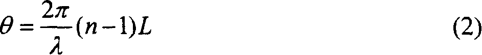
[0059] 2. Find a suitable Taber illuminator: In this embodiment, M=7, and the compression ratio of the corresponding Taber illuminator is 7. This value is closest to the Taber illuminator with a compression ratio of 3×3=9, so two redundant images need to be added to make M=9. According to the theoretical knowledge of the fractional Taber effect in the prior art [2], the phase distribution shown in Figure 7 can realize periodic illumination with a compression ratio of 9 at a distance of 1 / 6 Taber, and the illumination spot is shown in Figure 7 Shaded and white parts ...
PUM
Abstract
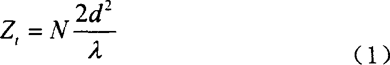
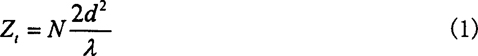
A multi-optical function calculation holographic device and its manufacturing method, its composition includes a phase plate containing the required M (M≥2) optical functions and a corresponding Taber illuminator, the Taber illuminator is a The phase plate is periodically arranged, the compression ratio of the Taber illuminator is m×m≥M, and the distance between the multi-optical function phase plate and the Taber illuminator is a fractional or integer Taber distance Z that can realize periodic illumination t , its production method includes the following steps: ① according to the needs, use the optimization algorithm to find out the phase distribution φ of the required multi-optical function M , where M is the number of optical functions to be realized; ②Find a suitable Taber illuminator from M, ③Pair the phase φ obtained in step ① according to the periodicity of the illumination light of the Taber illuminator M Recode to obtain a period, and then expand the period in space to make it have the same number of periods as the Taber illuminator to obtain the final multi-function phase plate; ④ Processing of the Taber illuminator and multi-function phase plate.
Description
Technical field: [0001] The invention relates to computational holography, in particular to a multi-optical function computational holographic device and a manufacturing method thereof. Background technique: [0002] Computational holographic elements are micro-optics based on diffractive optics. Different from traditional optical components, its design process requires the help of certain optimization algorithms and powerful computing power of computers. Its processing is compatible with modern microelectronic processing technology. [0003] Computational holographic elements have a wide range of applications in practice, such as wavefront shaping in laser technology, beam splitters, and laser shows. Computational holographic elements have the advantages of small size, light weight, high diffraction efficiency, and can be mass-produced at low cost. [0004] In general, computational holographic elements can only achieve a single optical function. The deformable diffract...
Claims
Application Information
Patent Timeline
Application Date:The date an application was filed.
Publication Date:The date a patent or application was officially published.
First Publication Date:The earliest publication date of a patent with the same application number.
Issue Date:Publication date of the patent grant document.
PCT Entry Date:The Entry date of PCT National Phase.
Estimated Expiry Date:The statutory expiry date of a patent right according to the Patent Law, and it is the longest term of protection that the patent right can achieve without the termination of the patent right due to other reasons(Term extension factor has been taken into account ).
Invalid Date:Actual expiry date is based on effective date or publication date of legal transaction data of invalid patent.
Patent Type & AuthorityPatents(China)
IPC IPC(8): G02B5/32G03H1/04
Inventor周常河戴恩文刘立人
OwnerSHANGHAI INST OF OPTICS & FINE MECHANICS CHINESE ACAD OF SCI

