
An Imaging Method to Realize High Spatial Bandwidth Product

An imaging method and high-space technology, applied in the fields of computational photography and image processing, imaging system design, and high-spatial bandwidth product imaging. problems, to achieve the effect of reducing design difficulty and production cost, reducing design difficulty, and increasing space-bandwidth product

Active Publication Date: 2020-05-01
NANJING UNIV
View PDF17 Cites 0 Cited by
  • Summary
  • Abstract
  • Description
  • Claims
  • Application Information

AI Technical Summary

Problems solved by technology

There will be two problems: first, in an imaging system that requires a high spatial bandwidth product, the design cost to eliminate most of the aberration blur is quite high, and a large number of lenses need to be assembled, and the material of the lens is also limited. Very high requirements, the difficulty of selecting design parameters will also rise sharply with the complexity of the system
Therefore, the price of high-end lenses can cost tens of thousands, and it is even more difficult to design lenses for special application scenarios (such as satellite imaging). Second, in small application scenarios such as mobile phones, the space available for lenses is small, and it is difficult to design complex systems. Therefore, this type of imaging equipment is generally accompanied by more distortion, which is difficult to meet the application requirements, and usually relies on subsequent algorithms to adjust it

Method used

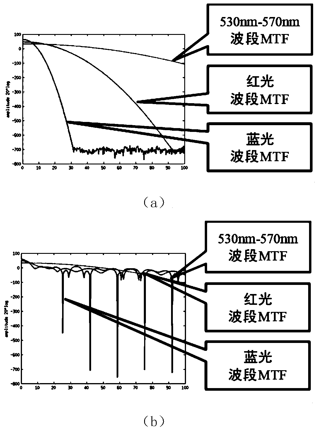

Image

  • An Imaging Method to Realize High Spatial Bandwidth Product
  • An Imaging Method to Realize High Spatial Bandwidth Product
  • An Imaging Method to Realize High Spatial Bandwidth Product

Examples


Embodiment

[0026] The imaging method for realizing the high spatial bandwidth product of this embodiment, the specific steps are as follows:

[0027] Step 1, since the green channel in the natural image contains relatively high energy, this embodiment selects the 520nm band as the center frequency (λ). The lens adopts a large aperture lens, and the aperture value F is set to 1.4, which is determined by the optical resolution limit formula:

[0028] σ=1.22λF

[0029] It can be calculated that at this frequency, the resolution limit can reach 888.16nm. The lens parameters can be calculated by substituting the corresponding values ​​into the ZEMAX optical design software, and the optical path diagram of the lens can be referred to figure 1 .

[0030] Step 2, design the color filter array (CFA): RGλB, where RGB is an ordinary red, green and blue three-color filter, and λ is a band-pass filter that matches the center frequency, and the pass-band frequency of the filter is selected as 500nm...


PUM


Abstract

The invention discloses an imaging method capable of implementing a high space-bandwidth product. The imaging method comprises the following specific steps of: (1) selecting a certain visible light frequency as a center frequency, and only optimizing an optical characteristic parameter of the center frequency without optimizing optical characteristic parameters of other frequencies; (2) designinga GRlambdaB color filtering arranger; and (3) generating a clear image by adopting a deep learning convolutional neural network model. According to the invention, an optical bandwidth product of an imaging system is effectively improved, and when imaging quality is ensured, the design difficulty and production cost of optical imaging equipment are reduced. The method not only can be used for large-aperture high-resolution imaging equipment, but also can be used for small-sized low-cost imaging equipment such as a mobile phone lens, a monitoring system and the like.

Description

technical field [0001] The invention relates to the fields of imaging system design, computational photography and image processing, in particular to the technical field of high space bandwidth product imaging. Background technique [0002] The purpose of the optical imaging system is to focus the light emitted by a point on a certain plane in space onto the imaging surface of the imaging system. In the actual imaging process, because the optical equipment cannot achieve the theoretical accuracy, various types of blur problems will occur. Blur mainly includes spherical aberration, coma, chromatic aberration, astigmatism and other types of distortion. The optical system generally eliminates distortion to a certain extent by combining multiple lenses with different refractive indices. There will be two problems: first, in an imaging system that requires a high spatial bandwidth product, the design cost to eliminate most of the aberration blur is quite high, and a large number...

Claims


Application Information

Patent Timeline
Patent Type & Authority Patents(China)
IPC IPC(8): G02B27/00H04N9/64G06T1/00
CPCG02B27/0012G02B27/005G06T1/0007H04N9/646
Inventor 岳涛徐伟祝
Owner NANJING UNIV
Learn More