Supercharge Your Innovation With Domain-Expert AI Agents!

Shadow mask frame of CRT

A cathode ray tube and shadow mask technology, which is applied to the shadow mask frame field of cathode ray tubes, can solve the problems of sensitive reaction, increasing the number of electron beam deflections, etc.

Inactive Publication Date: 2005-09-07
MERIDIAN SOLAR & DISPLAY
View PDF0 Cites 0 Cited by
  • Summary
  • Abstract
  • Description
  • Claims
  • Application Information

AI Technical Summary

Problems solved by technology

However, in case the electron beam passing through the electron beam passage hole on the shadow mask is fully exposed to the earth's magnetic field, and accordingly, the conventional cathode ray tube has a disadvantage that when the center portion of the face plate 3 and the center portion of the shadow mask 5 If the distance between the diagonal portion of the mask frame and the inner surface of the panel is longer, the electron beams 11R, 11G, and 11B are more sensitive to the magnetic field, thereby increasing the deflection amount of the electron beams

Method used


Image

  • Shadow mask frame of CRT
  • Shadow mask frame of CRT
  • Shadow mask frame of CRT

Examples


Embodiment Construction

[0054] Preferred embodiments of the present invention will be described in detail below, and each preferred embodiment is shown in the accompanying drawings.

[0055] Examples of implementations.

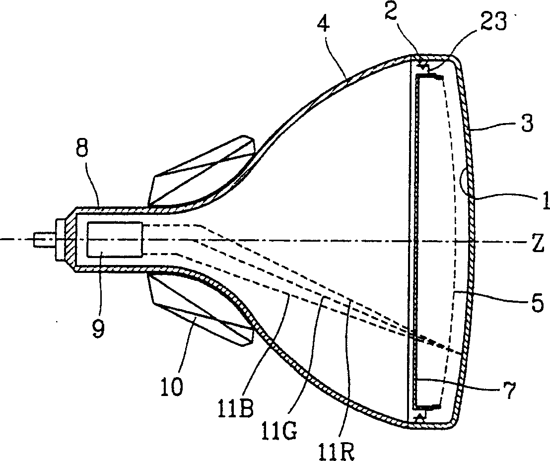
[0056] Such as Figure 9 As shown, the panel 3 having a substantially flat outer surface has a thickness Tv in the direction of the minor axis, a thickness Th in the direction of the major axis, a thickness Td in the direction of the diagonal axis, and thicknesses Tv, Th and Td towards the panel 3 The peripheral part becomes larger.

[0057] Therefore, the radius of curvature of the inner surface of the panel 3 is smaller than the radius of curvature of the outer surface of the panel 3 .

[0058] Such as Figure 10 As shown, the radius of curvature of the inner surface of the panel in the direction of the minor axis of the panel 3 is Rv', the radius of curvature in the direction of the major axis is Rh', and the radius of curvature in the direction of the diagonal axis is Rd'. F...


PUM


Abstract

A color cathode ray tube comprising a panel having a substantially flat outer surface, a funnel mounted on a rear side of the panel, a shadow mask including a plurality of electron beam through holes, and a mask frame for supporting the shadow mask, said mask frame satisfying the following condition: d / v>=0.9, d / h>=0.9 wherein d is a height of a center of a diagonal portion of the mask frame, h is a height of a center of a short side portion of the mask frame, and v is a height of a center of a long side portion of the mask frame.

Description

technical field [0001] The invention relates to a shadow mask frame of a cathode ray tube, in particular to a shadow mask frame of a cathode ray tube capable of improving screen purity margin. Background technique [0002] Generally speaking, if figure 1 A color cathode ray tube shown in , including: a panel 3, a funnel tube 4 connected to the panel 3 to form a vacuum space, a fluorescent screen 1 coated on the inner surface of the panel 3 to play a certain role in emitting light , an electron gun 9 installed at the rear of the funnel tube 4 and emitting electron beams 11R, 11G, and 11B, a shadow mask 5 installed at the rear of the panel 3 and at a certain distance from the fluorescent screen 1, and a shadow mask for fixing / supporting 5, an elastic support member 23 and a pin 2 for connecting the mask frame 7 to the panel 3, and a deflection yoke 10 for deflecting the electron beams 11R, 11G and 11B to the phosphor screen 1. [0003] Such as figure 2 and image 3 As sho...

Claims


Application Information

Patent Timeline
Patent Type & Authority Patents(China)
IPC IPC(8): H01J29/07
CPCH01J29/073H01J2229/0722
Inventor 崔澳勇
Owner MERIDIAN SOLAR & DISPLAY
Features
  • R&D
  • Intellectual Property
  • Life Sciences
  • Materials
  • Tech Scout
  • Unparalleled Data Quality
  • Higher Quality Content
  • 60% Fewer Hallucinations
Learn More