Supercharge Your Innovation With Domain-Expert AI Agents!

Lens cap assembly

A technology of lens caps and components, applied to optical and photographic filters, instruments, etc., can solve problems such as loss of lens caps 108, trouble, inconvenience, etc.

Inactive Publication Date: 2006-01-04
QISDA CORP
View PDF0 Cites 0 Cited by
  • Summary
  • Abstract
  • Description
  • Claims
  • Application Information

AI Technical Summary

Problems solved by technology

[0005] It should be noted that when the user operates the projector 102 and places the lens cover 108 on the side of the projector 102, since the lens cover 108 is not connected with the casing 104, the phenomenon of losing the lens cover 108 is easy to occur. , quite inconvenient
In addition, when the user wants to insert and remove the lens cover 108, the user must first support the case 104 with one hand, and then the other hand of the user can smoothly insert and remove the lens cover 108 on the side plate 104a of the case, which is very troublesome.

Method used


Image

  • Lens cap assembly
  • Lens cap assembly
  • Lens cap assembly

Examples


Embodiment Construction

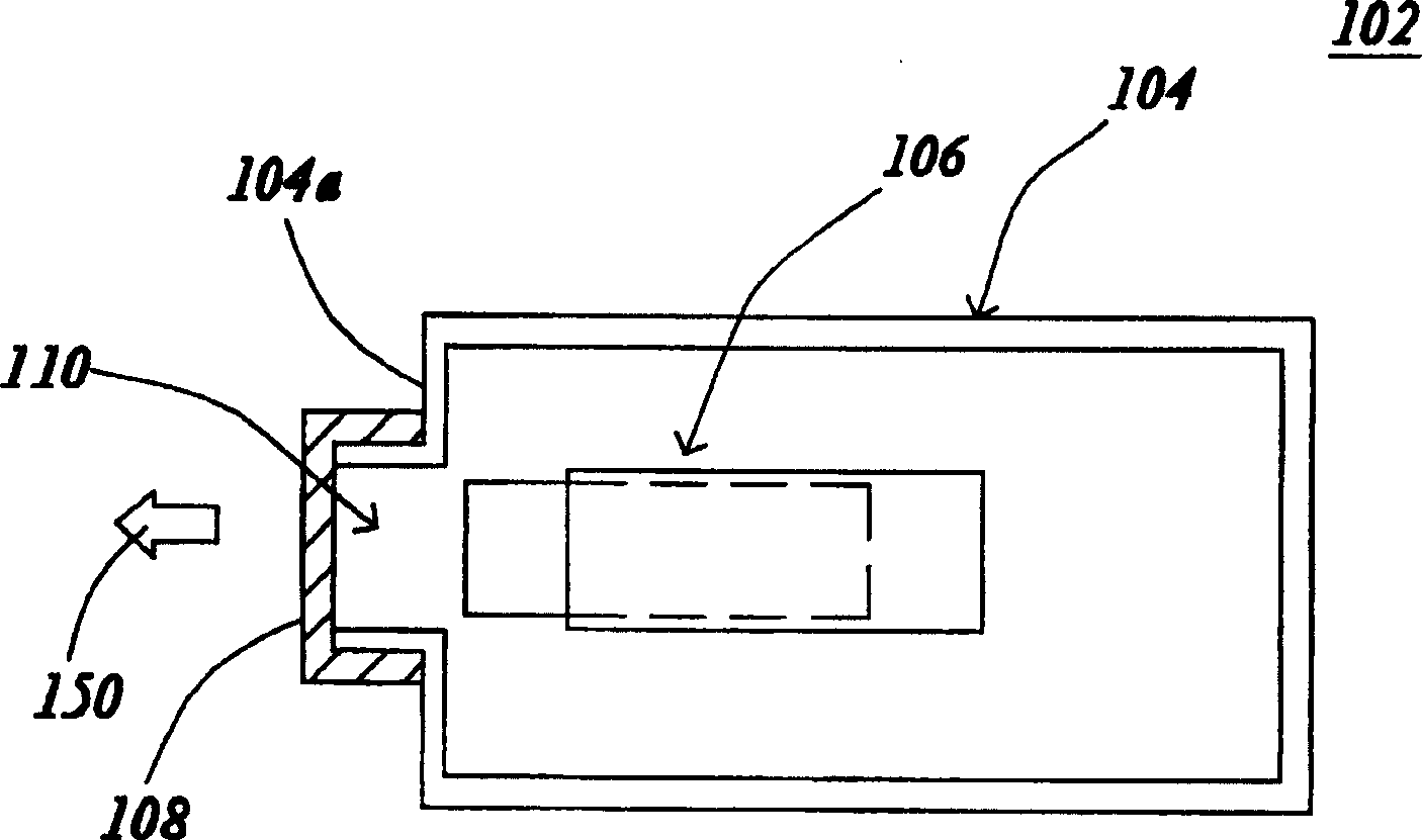
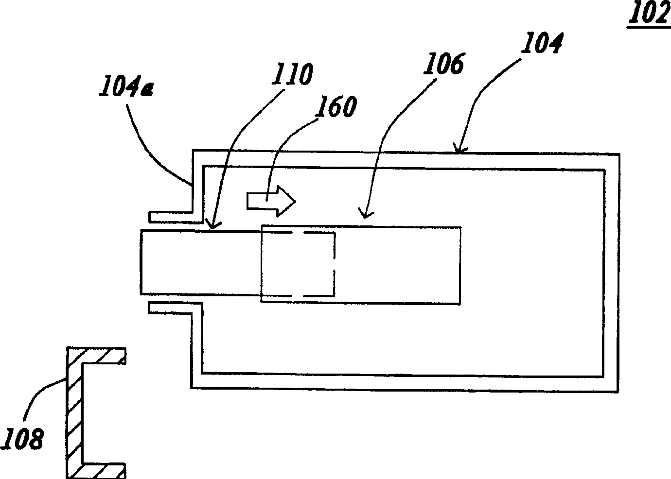
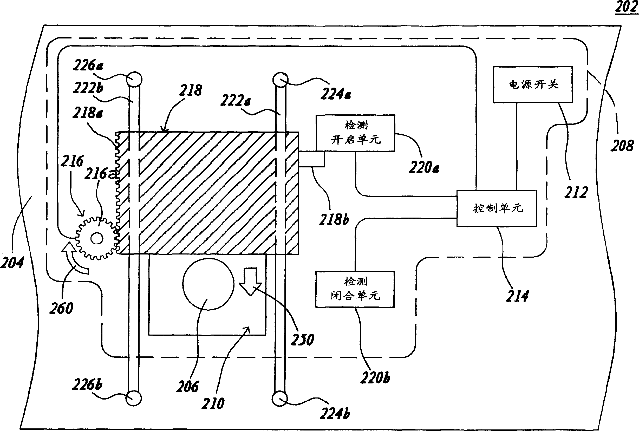
[0032] The present invention specially designs a lens cover assembly for the user to open and close the projection opening of the projector. The lens cover assembly includes a power switch, a lens cover, a transmission unit, a detection closing unit, a detection opening unit and a control unit, a power switch, a transmission The unit, the detection closing unit and the detection opening unit are all connected with the control unit.

[0033] Wherein, when the user turns on or off the power switch, the control unit will drive the transmission unit to rotate, so that the lens cover moves forward or backward. When the lens cover touches the detection opening unit or the detection closing unit, the control unit will drive the transmission unit to stop rotating, so that the lens cover opens or closes the projection opening. As for the practical application of the lens cap assembly of the present invention, it will be described as follows with preferred embodiments of the accompanyin...


PUM


Abstract

The lens cap assembly for projector includes power switch, lens cap, transmission unit, detection and clkosing unit, detection and opening unit and control unit connected to the power switch and the other units. When the power switch is turned on or off, the control unit will rotate the transmission unit to make the lens cap move forwards or backwards. When the lens cap touches with the detection and closing unit or the detection and opening unit, the control unit will stop the transmission unit to open or close the lens cap.

Description

technical field [0001] The present invention relates to a lens cover assembly, and in particular to a lens cover assembly which can be easily operated by a user to drive the lens cover to open or close a projection opening. Background technique [0002] Modern people often use projectors for presentations, conferences, and educational training. Especially, when users connect the projectors to computers, users can evolve from traditional monotonous flat projections to multimedia computer presentations. Participants can use the projector to project the presentation materials in the computer on a larger plane or screen, so that the attendees can clearly see the presentation materials, which is quite convenient. Among them, the projector must use the lens to project the presentation data to the outside world. If the surface of the lens is scratched or covered with dust, the image projected by the projector through the lens will be blurred. Therefore, the...

Claims


Application Information

Patent Timeline
Patent Type & Authority Patents(China)
IPC IPC(8): G03B21/14G03B11/04
Inventor 李长坚
Owner QISDA CORP
Features
  • R&D
  • Intellectual Property
  • Life Sciences
  • Materials
  • Tech Scout
  • Unparalleled Data Quality
  • Higher Quality Content
  • 60% Fewer Hallucinations
Learn More