Supercharge Your Innovation With Domain-Expert AI Agents!

Casing fastening structure

A technology of connecting structure and casing, applied in the field of casing buckle structure, can solve problems such as cost of gluing equipment and colloidal material, poor bonding degree between the first casing and the second casing, easy separation, etc.

Active Publication Date: 2008-01-16
ASUSTEK COMPUTER INC
View PDF3 Cites 0 Cited by
  • Summary
  • Abstract
  • Description
  • Claims
  • Application Information

AI Technical Summary

Problems solved by technology

Therefore, it is also necessary to spend the cost of gluing equipment and colloidal materials
In addition, if the ribs are unevenly irradiated by ultrasonic waves or the glue is applied unevenly, the degree of bonding between the first casing and the second casing will become poor, and separation will easily occur
In addition, not only rechargeable batteries, but also the casings of many products are bonded and fixed by the above-mentioned ultrasonic irradiation ribs or glue coating. In this way, the above-mentioned shortcomings cannot be avoided.

Method used


Image

  • Casing fastening structure
  • Casing fastening structure
  • Casing fastening structure

Examples


Embodiment 1

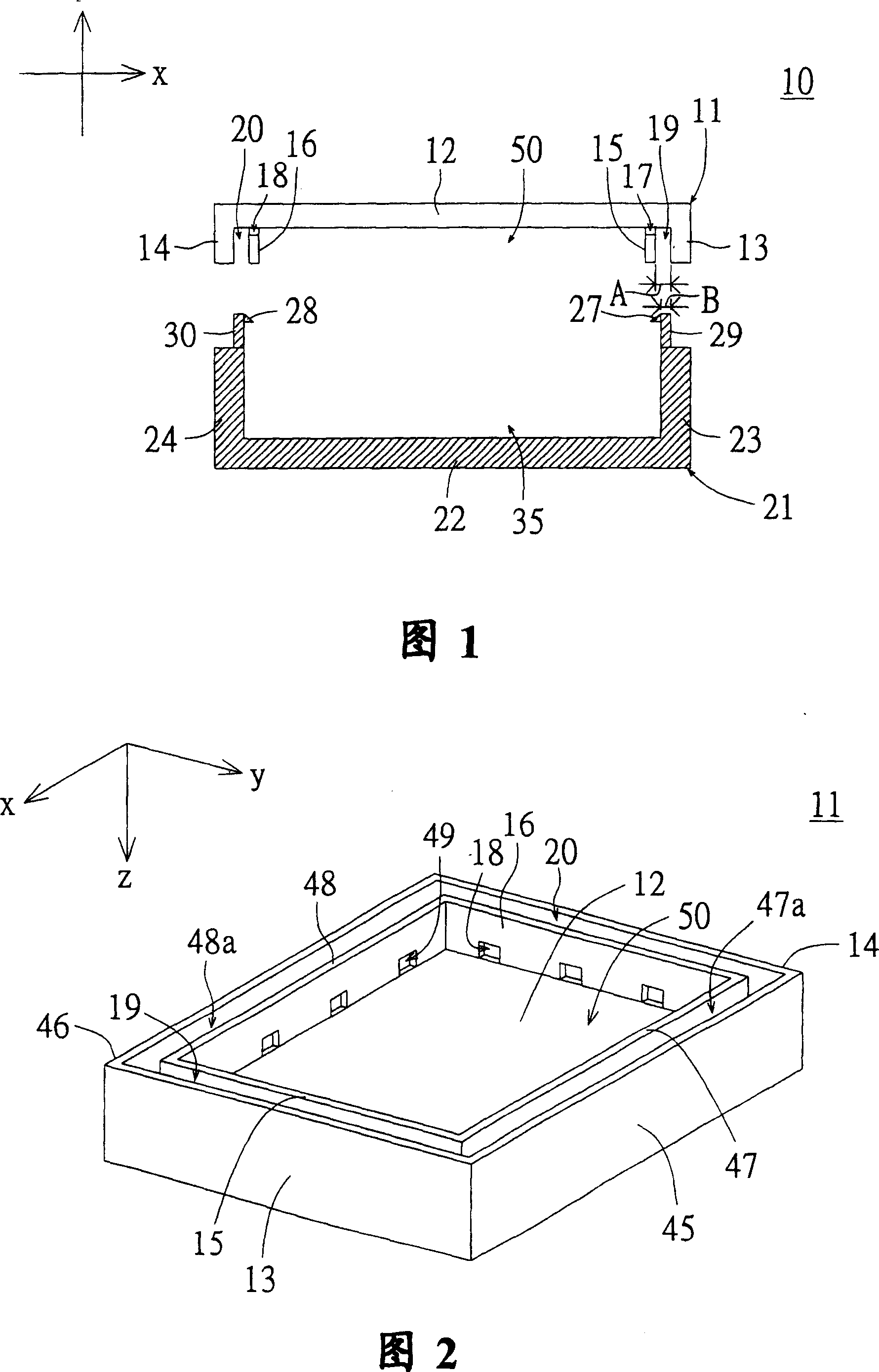
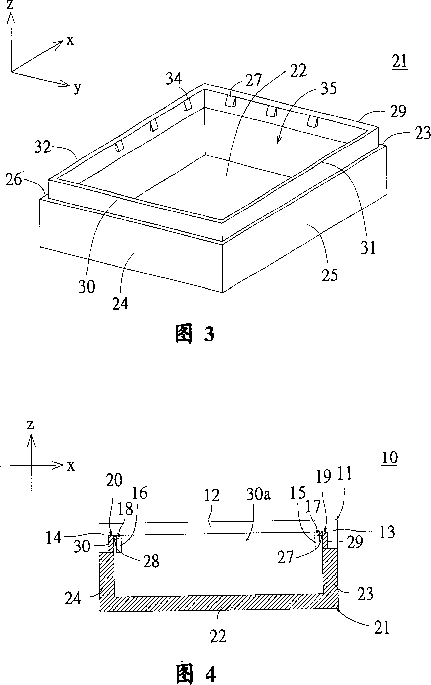
[0020] Please refer to FIG. 1 , which is an exploded cross-sectional view of a casing with a casing fastening structure according to Embodiment 1 of the present invention. In FIG. 1, the casing 10 includes a first casing 11, a second casing 21 and a casing fastening structure, and the casing fastening structure is used to fasten the first casing 11 and the second casing 21. , so that the first casing 11 and the second casing 21 cannot be separated after being combined. As for the design of the fastening structure of the case in this embodiment, it will be described in more detail later.

[0021] As shown in Figures 1 to 2, Figure 2 is a schematic perspective view of the first casing in Figure 1 in an upside-down state, and the first casing in Figure 1 is a view viewed in the -y direction with the xz plane as the section plane 2. The inverted structure of the first casing. The first casing 11 includes a first bottom plate 12 , first side plates 13 , 14 , 45 and 46 , and first...

Embodiment 2

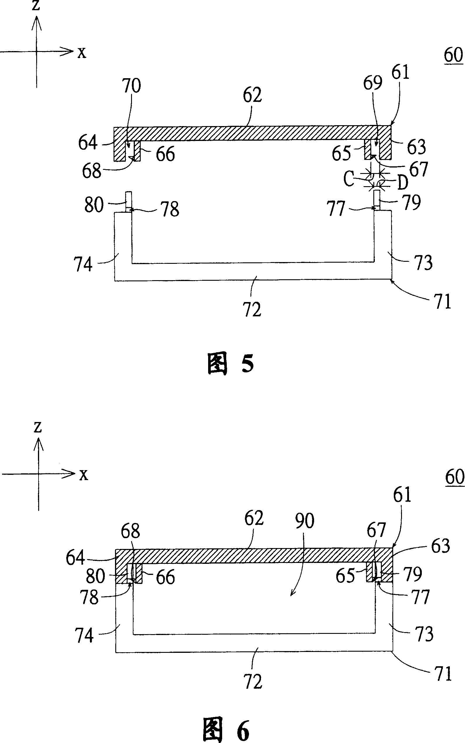
[0030] Please refer to FIG. 5 , which is an exploded cross-sectional view of a casing with a fastening structure for the casing according to Embodiment 2 of the present invention. In FIG. 5, the casing 60 includes a first casing 61, a second casing 71 and a casing fastening structure, and the casing fastening structure is used to fasten the first casing 61 and the second casing 71. , so that the first casing 11 and the second casing 71 cannot be separated after being combined. As for the design of the fastening structure of the case in this embodiment, it will be described in more detail later.

[0031] The first casing 61 at least includes a first bottom plate 62 , first side plates 63 and 64 , and first retaining walls 65 and 66 . Both the first side panels 63 and 64 are vertically disposed on the first bottom panel 12 , and the first side panel 63 is opposite to the first side panel 64 . The first retaining walls 65 and 66 are vertically disposed on the first bottom plate...


PUM


Abstract

The invention relates to a carbine lock joint structure used to lock joint a first carbine and a second carbine. The first carbine has a first flank plate. The carbine lock joint structure comprises a first retaining wall and a second retaining wall, wherein the first retaining wall is positioned inside the first carbine and parallel with the first frank plate. The first retaining wall has a first lock joint part; the second retaining wall is positioned inside the second carbine and has a corresponding second lock joint part. The second lock joint part is used to lock joint the first lock joint part so that the first carbine combines with the second carbine when the second retaining wall inserts between the flank plate and the first retaining wall.

Description

technical field [0001] The present invention relates to a fastening structure of a casing, and in particular to a fastening portion of a first retaining wall of a first casing and a second fastening portion of a second retaining wall of a second casing. The casing fastening structure is interlocked to combine the first casing and the second casing. Background technique [0002] In today's era of rapid technological development, portable electronic devices have become an indispensable part of modern people's daily life. Especially notebook computers, which are thin, light, portable, and have the characteristics of rechargeable batteries, can allow modern people to handle work or daily life anytime, anywhere, which is quite convenient. [0003] The rechargeable battery is usually sealed in a case, and the case for sealing the rechargeable battery is formed by adhering a first case and a second case. In the process of sealing the rechargeable battery in the casing, firstly, t...

Claims


Application Information

Patent Timeline
Patent Type & Authority Patents(China)
IPC IPC(8): G06F1/16H05K5/06
Inventor 陈镱仁
Owner ASUSTEK COMPUTER INC
Features
  • R&D
  • Intellectual Property
  • Life Sciences
  • Materials
  • Tech Scout
  • Unparalleled Data Quality
  • Higher Quality Content
  • 60% Fewer Hallucinations
Learn More