Semiconductor component having encapsulated, bonded, interconnect contacts

a technology of encapsulation and bonded contacts, which is applied in the direction of semiconductor devices, semiconductor/solid-state device details, electrical apparatus, etc., can solve the problems of entanglement, affecting the bonding of terminal contacts, and affecting the bonding of interconnect contacts, etc., to achieve the effect of facilitating bonding of terminal contacts

Inactive Publication Date: 2005-06-14
MICRON TECH INC
View PDF17 Cites 139 Cited by
  • Summary
  • Abstract
  • Description
  • Claims
  • Application Information

AI Technical Summary

Benefits of technology

[0009]The component includes a semiconductor die having a pattern of die contacts, such as bond pads or redistribution pads, in electrical communication with integrated circuits contained on the die. The component also includes interconnect contacts bonded to the die contacts, and encapsulated in an insulating layer. The interconnect contacts can comprise posts, studs, bumps, balls or ribbons formed using conventional equipment. The component also includes terminal contacts bonded directly to the interconnect contacts. In addition, the interconnect contacts can include metallization layers to facilitate bonding of the terminal contacts.

Problems solved by technology

As the components become smaller, and the terminal contacts more dense, fabrication methods become more difficult.
These interconnect contacts are relatively fragile and can separate from the die contacts and become entangled.
In this case the polymer substrate may be difficult to align and attach to the dice.

Method used


Image

  • Semiconductor component having encapsulated, bonded, interconnect contacts
  • Semiconductor component having encapsulated, bonded, interconnect contacts
  • Semiconductor component having encapsulated, bonded, interconnect contacts

Examples


Embodiment Construction

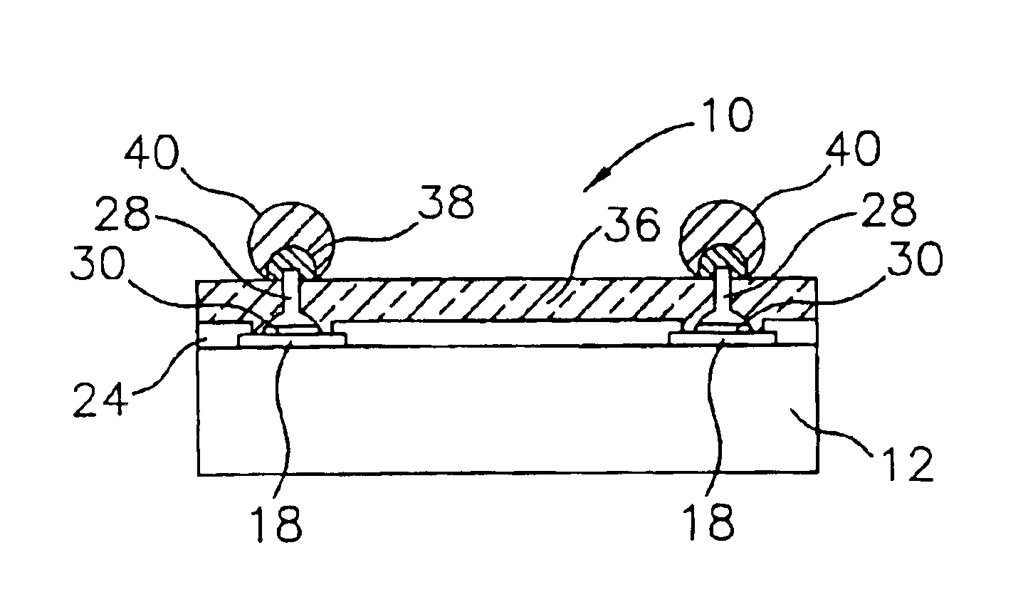
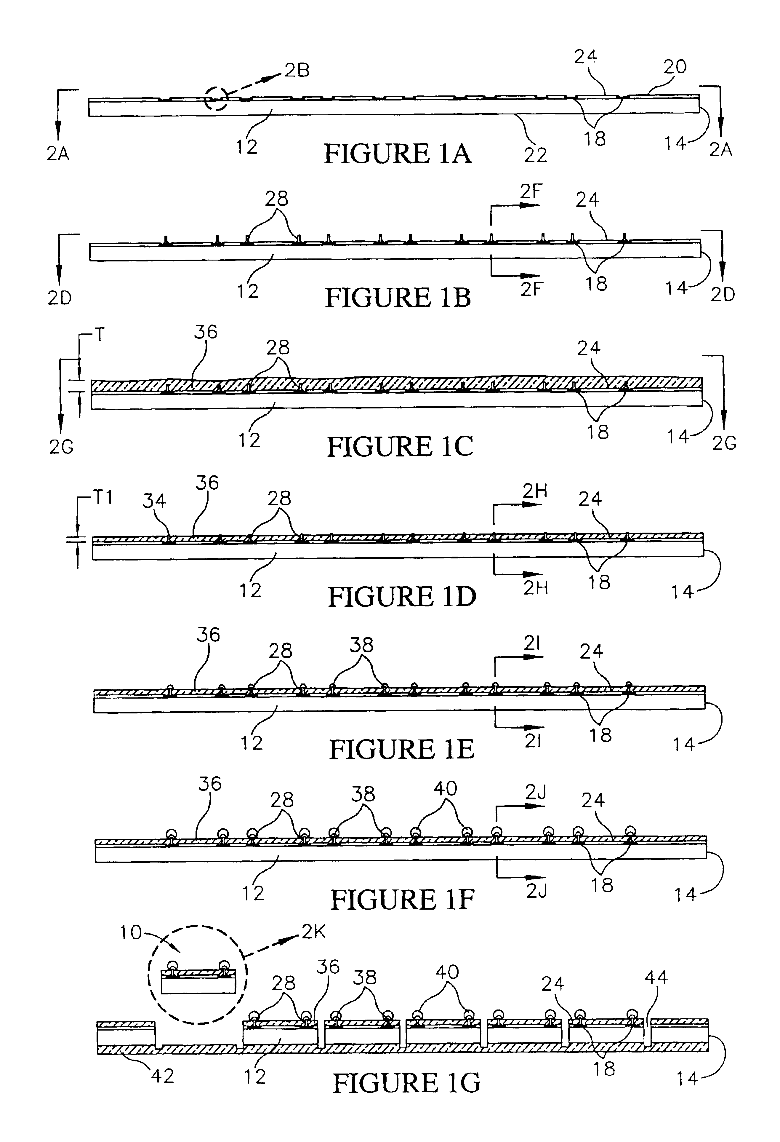
[0040]As used herein, the term “semiconductor component” refers to an electronic element that includes a semiconductor die. Exemplary semiconductor components include semiconductor packages, BGA devices, flip chip devices and bumped semiconductor dice.

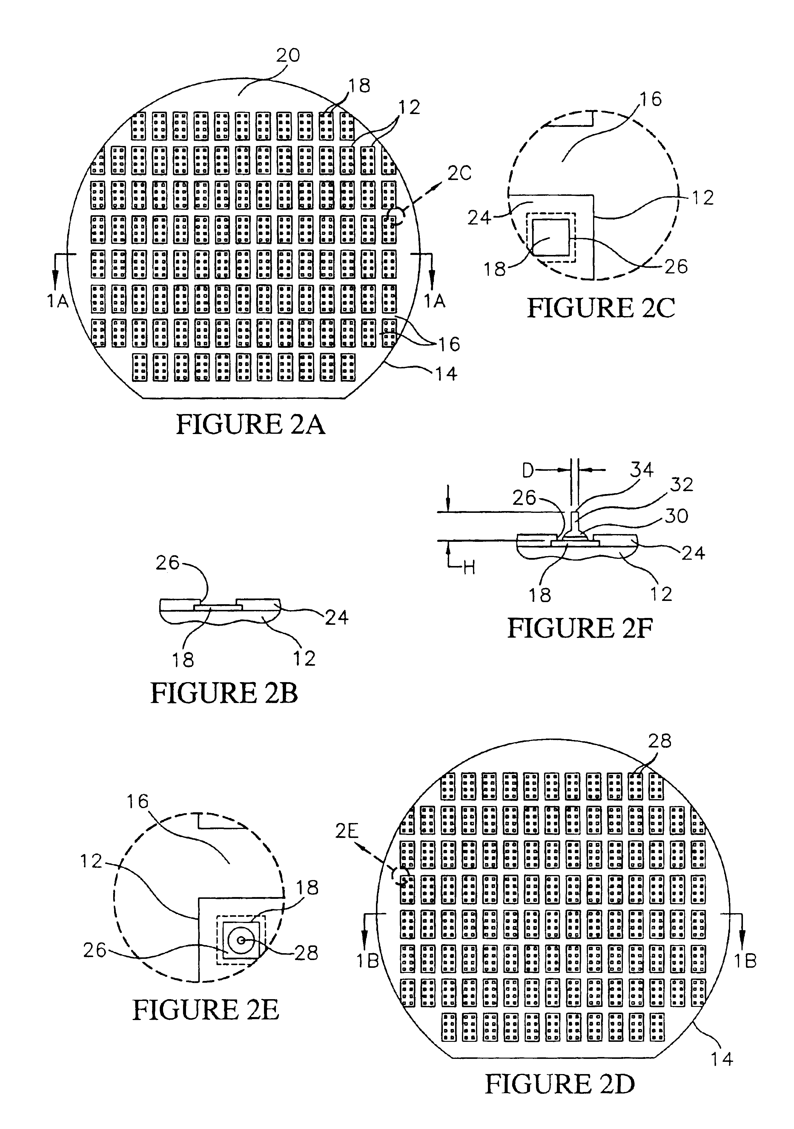
[0041]Referring to FIGS. 1A-1G, steps in the method for fabricating a semiconductor component 10 (FIG. 1G) in accordance with the invention are illustrated. Initially, as shown in FIGS. 1A and 2A, a plurality of semiconductor dice 12 are provided, for fabricating a plurality of semiconductor components 10 (FIG. 1G). The dice 12 can comprise conventional semiconductor dice having a desired configuration. For example, each die 12 can comprise a dynamic random access memory (DRAM), a static random access memory (SRAM), a flash memory, a microprocessor, a digital signal processor (DSP) or an application specific integrated circuit (ASIC). The dice 12 and the components 10 can have any polygonal shape. In the illustrative embodiment, the di...


PUM


Abstract

A semiconductor component includes a die having a pattern of die contacts, and interconnect contacts bonded to the die contacts and encapsulated in an insulating layer. The component also includes terminal contacts formed on tip portions of the interconnect contacts. Alternately the component can include conductors and bonding pads in electrical communication with the interconnect contacts configured to redistribute the pattern of the die contacts. A method for fabricating the component includes the steps of forming the interconnect contacts on the die contacts, and forming the insulating layer on the interconnect contacts while leaving the tip portions exposed. The method also includes the step of forming the terminal contacts on the interconnect contacts, or alternately forming the conductors and bonding pads in electrical communication with the interconnect contacts and then forming the terminal contacts on the bonding pads.

Description

CROSS REFERENCE TO RELATED APPLICATIONS[0001]This application is a division of Ser. No. 10 / 193,567, filed Jul. 11, 2002, now U.S. Pat. No. 6,803,303 B1.FIELD OF THE INVENTION[0002]This invention relates generally to semiconductor manufacture and packaging. More particularly, this invention relates to a semiconductor component having encapsulated bonded, interconnect contacts, to a method for fabricating the component, and to systems incorporating the component.BACKGROUND OF THE INVENTION[0003]Semiconductor components, such as chip scale packages, BGA devices, flip chip devices, and bumped dice include terminal contacts such as bumps, balls, pins or pads. The terminal contacts can be formed directly on the dice, or on substrates attached to the dice. Typically, the components also include protective layers which insulate one or more surfaces of the dice, and provide electrical insulation for the terminal contacts, and for conductors associated with the terminal contacts. The quality,...

Claims


Application Information

Patent Timeline
Patent Type & Authority Patents(United States)
IPC IPC(8): H01L23/28H01L23/31H01L21/68H01L21/67
CPCH01L21/6836H01L23/49531H01L23/49575H01L24/06H01L24/11H01L24/12H01L24/94H01L23/3114H01L24/27H01L2224/11334H01L2221/68327H01L2224/0401H01L2224/04042H01L2224/06136H01L2224/1134H01L2224/13022H01L2224/13083H01L2224/13099H01L2224/13111H01L2224/136H01L2224/16H01L2224/274H01L2924/01013H01L2924/01022H01L2924/01029H01L2924/0103H01L2924/01046H01L2924/01047H01L2924/0105H01L2924/01074H01L2924/01077H01L2924/01078H01L2924/01079H01L2924/01082H01L2924/01322H01L2924/014H01L2924/14H01L2924/1433H01L2224/02333H01L2224/13109H01L2924/01005H01L2924/01006H01L2924/01019H01L2924/01033H01L2924/12042H01L2924/181B33Y80/00H01L2924/00H01L2924/00012H01L21/44H01L23/48
Inventor HIATT, WILLIAM M.FARNWORTH, WARREN M.WATKINS, CHARLES M.SINHA, NISHANT
Owner MICRON TECH INC
Why Eureka
Try Eureka