Earphone detecting circuit

A technology for detecting circuits and earphones, applied to stereo communication earphones, stereo circuit arrangements, etc., can solve the problems of large circuit size and inability to effectively detect the existence of earphones, and achieve the effect of reducing the size and retaining convenience

Inactive Publication Date: 2006-07-05
HTC CORP
View PDF0 Cites 0 Cited by
  • Summary
  • Abstract
  • Description
  • Claims
  • Application Information

AI Technical Summary

Problems solved by technology

[0006] To sum up, the deficiencies of the known technology can be roughly divided into two types, one is that although the presence of the earphone can be detected, the circuit volume is relatively large; the other is that although the circuit volume is small, it cannot effectively detect Whether the headset is present

Method used


Image

  • Earphone detecting circuit
  • Earphone detecting circuit
  • Earphone detecting circuit

Examples


Embodiment Construction

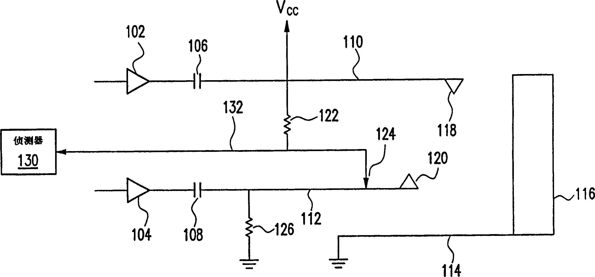
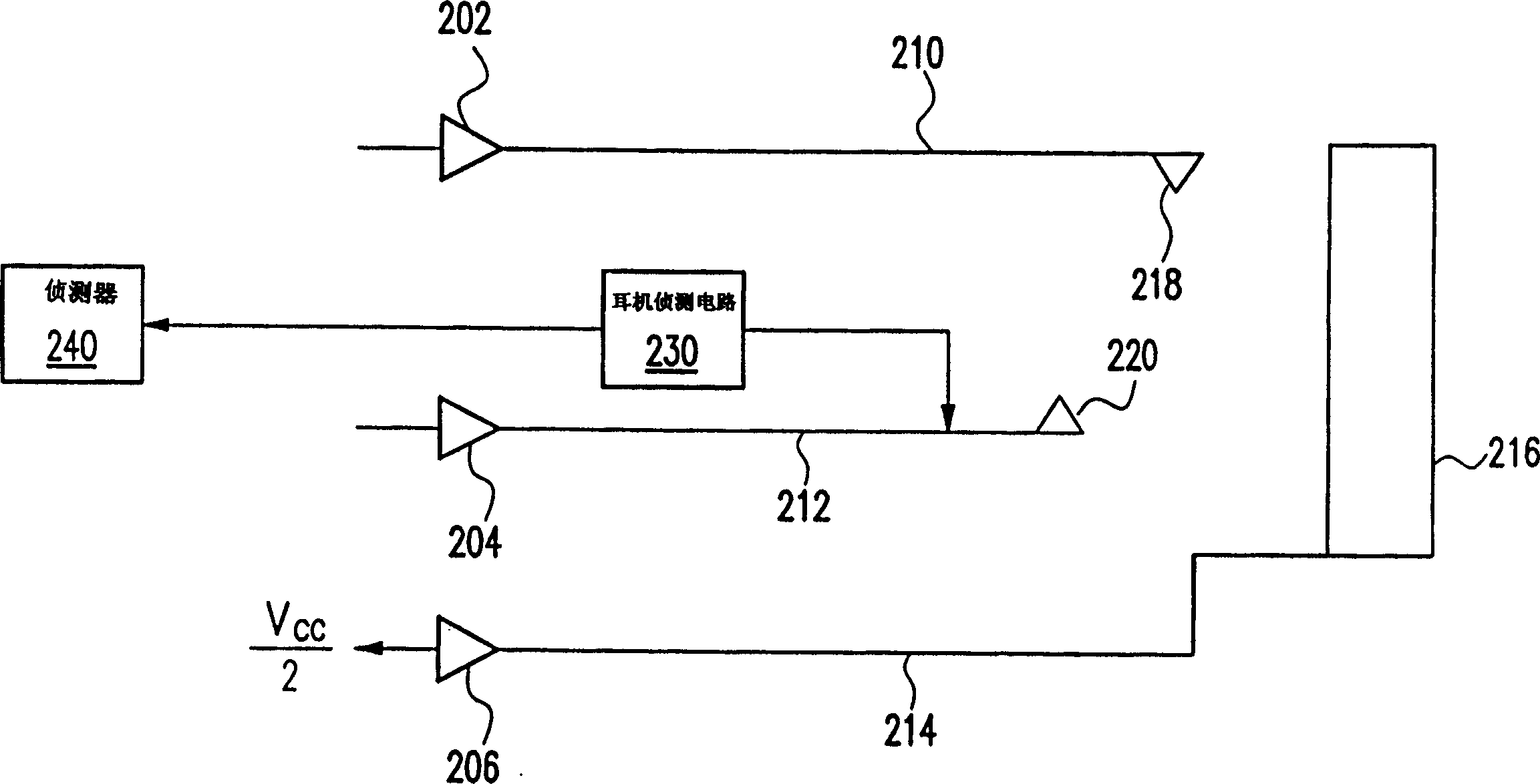
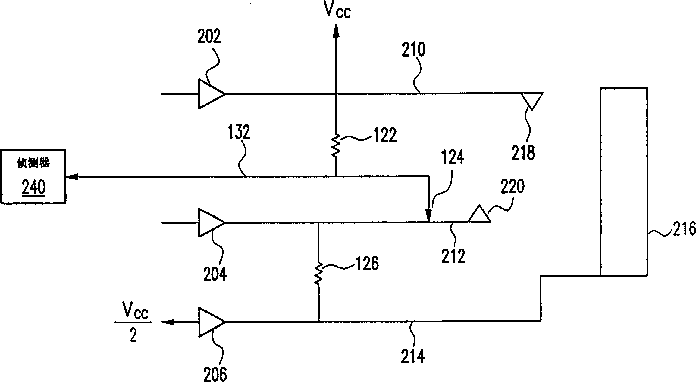
[0033] In order to enable those skilled in the art to easily understand the technical contents of the present invention, hereby Figure 2A The headphone drive circuit shown is a brief introduction. exist Figure 2A In this case, the headphone driving circuit is not actually grounded, but is based on the voltage of the virtual ground line 214 (V cc / 2) is the virtual ground voltage. In this case, the assumption is that figure 1 As shown, the part made up of the resistors 122 and 126 and the detection circuit 132 is used as the earphone detection circuit 230 here, and the overall circuit is as follows Figure 2B shown. Note that in Figure 2B in, with figure 1 or Figure 2A Components of the same number are similar to figure 1 or Figure 2A Components with corresponding numbers.

[0034] From Figure 2B It can be known that when the earphone is not inserted, the potential of the audio signal transmission line 212 will be V cc / 2, so the potential obtained by the dete...


PUM


Abstract

An earphone detection circuit consists of a transistor with four ends and its first end being electrically connected with its fourth end and a operation voltage. The first resistance has its one end being electrically connected with the first end of the transistor and its another end with the second end of the transistor, the second resistance has its one end being electrically connected with the third end of the transistor and its another end with earthing, the third resistance has its one end being electrically connected with the second end of the transistor and its another end with the detection end of earphone driving circuit, a capacity has its one end being electrically connected with the second end of the transistor and its an other end with earthing, and a detector is electrically connected with the third end of the transistor.

Description

technical field [0001] The present invention relates to an earphone detection circuit, and in particular to an earphone detection circuit when the common ground terminals of the left and right sound channels of the earphone cannot be actually grounded. Background technique [0002] The various audio providing devices used at present, such as: tape recorders, video recorders, TVs, or even portable computers, etc., most of them will provide two kinds of audio output channels, one of which is the built-in speakers of these audio providing devices, and The other is a headphone jack, so that users can adopt different audio listening methods in response to different environmental needs. In addition, these audio providing devices generally provide a function of automatically switching audio listening modes. In other words, when the audio provider finds that there is an earphone or other external output device plugged into the earphone jack, it will transmit the audio signal to the...

Claims


Application Information

Patent Timeline
Patent Type & Authority Patents(China)
IPC IPC(8): H04R5/033H04R5/04
Inventor 梁展立
Owner HTC CORP
Why Eureka
Try Eureka