Method of turbine operation

An operation method and turbine technology, which is applied to steam engine devices, engine components, machines/engines, etc., can solve problems such as fuel quality fluctuations, turbine damage, and impact on operation, and achieve the effect of avoiding the danger of false start protection functions

Inactive Publication Date: 2006-11-08
SIEMENS AG
View PDF1 Cites 0 Cited by
  • Summary
  • Abstract
  • Description
  • Claims
  • Application Information

AI Technical Summary

Problems solved by technology

When the specified temperature range is exceeded, for example between 450°C and 550°C, it may affect the operation and cause damage to the turbine
Fluctuations in the live steam temperature are due to various causes, for example due to fluctuations in the quality of the fuel with which the live steam is heated by means of its combustion gases, or due to problems with the boiler or with the temperature regulation of the boiler

Method used


Image

  • Method of turbine operation
  • Method of turbine operation
  • Method of turbine operation

Examples


Embodiment Construction

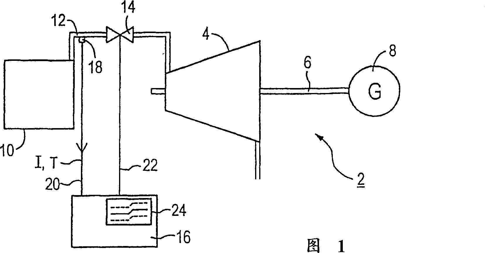
[0029] The turbine arrangement 2 according to FIG. 1 includes a turbine 4 , in particular a steam turbine, which is connected via a shaft 6 to a generator 8 for generating electrical energy. Turbine 4 is driven by gaseous medium, especially live steam. Live steam is generated in the boiler 10 and fed from there via a steam line 12 to the turbine 4 . The steam line 12 can be blocked by means of a valve 14, in particular a quick closing valve. The turbine unit 2 also includes a protective device 16 and a temperature sensor 18 which, in the exemplary embodiment according to FIG. 1 , is mounted directly on the steam line 12 in the region of the boiler 10 . The protection device 16 is connected to the temperature sensor 18 via a data line 20 and to the valve 14 via a control line 22 . Turbine protection is activated by triggering a snap shut down via control line 22 if required.

[0030] The temperature sensor 18 is used to detect the actual value I of the temperature T of the l...


PUM


Abstract

In order to keep the thermal load of the turbine (4) within acceptable limits, the invention proposes to monitor the temperature (T) of the medium fed to the turbine (4), especially the live steam, over time. Preferably, the feed of live steam to the turbine (4) is automatically and quickly shut off when a maximum temperature gradient (dT / dt(max)) is exceeded.

Description

technical field [0001] The invention relates to a method for operating a turbine. Background technique [0002] In industrial equipment, such as power generation equipment, a gaseous medium is supplied to the turbine in order to drive the turbine. The turbine is usually connected to a generator for producing electrical energy or drives a compressor or a pump, for example. The gaseous medium in a steam turbine is live steam. This live steam is heated in a boiler connected upstream of the turbine before it is fed into the turbine. [0003] In document D1-US-A-4655041 (DEL VECCHIO RICHARD J ET AL April 7, 1987) a method and an apparatus for detecting and analyzing undesired temperature and pressure changes are described. Here, the temperature and pressure of the steam flowing into the turbine are periodically measured and compared with specified values. If it exceeds the specified value, it will alarm. The first alarm occurs when the temperature exceeds the specified maxim...

Claims


Application Information

Patent Timeline
IPC IPC(8): F01K7/16F01D17/08F01D17/24F01D21/12
CPCF01D17/085F01D21/12F01K7/165F05D2220/31F05D2270/112F05D2270/3032
Inventor 罗伯特·塞茨
Owner SIEMENS AG
Why Eureka
Try Eureka