Magnetic head

A technology of magnetic head and magnetic shielding layer, which is applied in the direction of magnetic recording head, magnetic head using thin film, magnetic recording, etc., can solve the problems of disadvantage of high-density information recording system, etc.

Inactive Publication Date: 2002-07-03
SAMSUNG ELECTRONICS CO LTD
View PDF0 Cites 4 Cited by
  • Summary
  • Abstract
  • Description
  • Claims
  • Application Information

AI Technical Summary

Problems solved by technology

Magnetic field concentration due to external magnetic fie...

Method used


Image

  • Magnetic head
  • Magnetic head
  • Magnetic head

Examples


Embodiment Construction

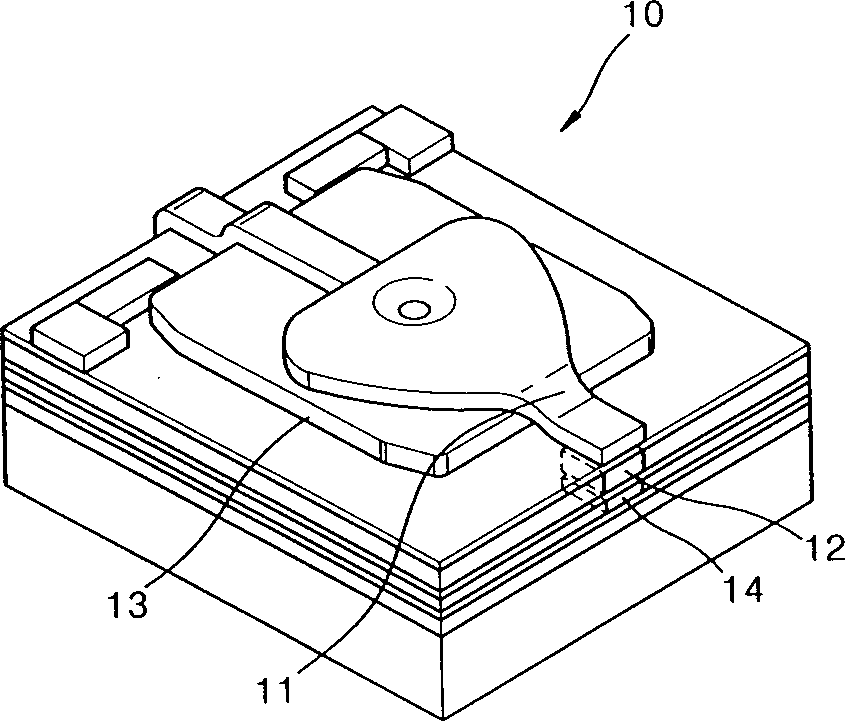
[0018] refer to Figure 4 , a multilayer stack structure for writing and reading information is formed on a substrate 101 . A magnetic shielding layer 150, which is a feature of the present invention, is formed on the topmost layer of the multilayer stack. A top pole 110 is formed under the magnetic shielding layer 150 and spaced a predetermined distance therefrom, and a bottom pole 120 is formed under the top pole 110 . A magnetoresistive head 140 is located below the bottom pole 120 . The magnetic shielding layer 150 is made of metal, preferably a magnetic material, and has a width greater than that of the top pole 110 or the bottom pole 120 .

[0019] Here, widths of upper and lower portions of the magnetic shielding layer 150 are preferably equal to each other. In case the widths of the upper and lower portions of the magnetic shielding layer 150 are different, they must be adjusted so that the intensity of the magnetic field concentrated at the edge portion is smaller ...


PUM


Abstract

Provided is a magnetic head including a bottom pole, a top pole spaced a predetermined distance apart from the bottom pole, an inductive write coil for forming a magnetic field at the bottom and top poles, and a magnetic shield layer positioned over the top pole.

Description

field of invention [0001] BACKGROUND OF THE INVENTION Field of the Invention The present invention relates to a magnetic head for writing / reading magnetic signals to / from a recording medium, and more particularly, to a magnetic head constructed so as not to generate magnetic field concentration due to an external magnetic field. Background technique [0002] A device for writing / reading magnetic signals to / from a recording medium, such as a hard disk drive, includes a magnetic head for writing and reading information. Such as figure 1 As shown in , a magnetic head 10 is mounted on a slider 20 provided at one end of a rotary arm 30, and is moved to a track at a desired position on a recording medium (not shown) by rotation of the rotary arm 30 for writing. or read operations. [0003] figure 2 for figure 1 An enlarged view of the magnetic head 10 shown in . Such as figure 2 As shown in , the magnetic head 10 includes a magnetoresistive head 14 for reading information ...

Claims


Application Information

Patent Timeline
IPC IPC(8): G11B5/127G11B5/11G11B5/31
CPCG11B5/11G11B5/3143G11B5/127
Inventor 金庸洙朴鲁烈
Owner SAMSUNG ELECTRONICS CO LTD
Why Eureka
Try Eureka