Straight line motor

A technology of linear motors and armatures, applied to electrical components, electromechanical devices, electric components, etc., can solve problems such as stator space loss

Inactive Publication Date: 2002-07-17
HITACHI LTD
View PDF1 Cites 8 Cited by
  • Summary
  • Abstract
  • Description
  • Claims
  • Application Information

AI Technical Summary

Problems solved by technology

In this way, there is a large loss

Method used


Image

  • Straight line motor
  • Straight line motor
  • Straight line motor

Examples


Embodiment Construction

[0026] Referring to Figure 1A to Figure 14 Preferred modes of the linear motor of the present invention will be described. In the different figures, the same reference numerals are used to designate the same and equivalent parts, components or entities.

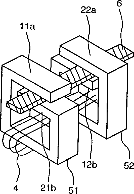
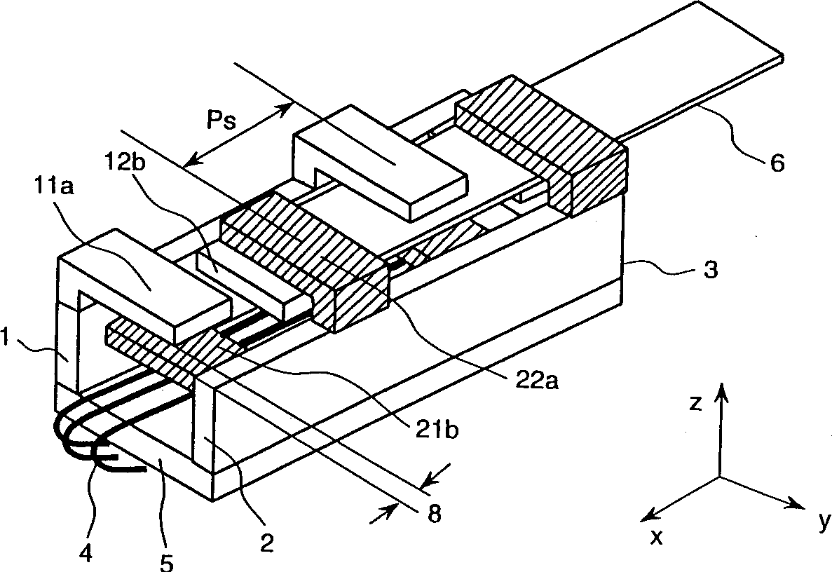
[0027] FIG. 1A illustrates the basic structure of an embodiment of the linear motor of the present invention, and FIG. 1B illustrates a multi-pole toothed linear motor expanded from the basic structure of the embodiment shown in FIG. 1A.

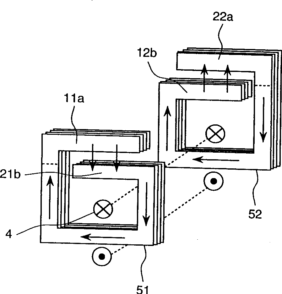
[0028] As shown in Fig. 1A, numeral 51 designates a core with a first opposing portion, and numeral 52 designates a core with a second opposing portion. The cores 51 and 52 are constructed such that the upper and lower magnetic poles of one of the cores 51 and 52 are opposite in polarity to the upper and lower magnetic poles of the other of the cores 51 and 52 .

[0029] The first opposing portion includes the upper magnetic pole teeth 11 a and the lower magnetic pole teeth 21 b of the c...


PUM


Abstract

A linear motor has an armature; a moving member movable relatively to the armature; first and second magnetic pole tooth trains each having magnetic pole teeth magnetically coupled to one of two magnetic poles of the moving element, the first and second magnetic pole tooth trains being separated from each other in a direction substantially perpendicular to a moving direction of the moving member; and third and fourth magnetic pole tooth trains each having magnetic pole teeth magnetically coupled to the other of the two magnetic poles of the moving element, the third and fourth magnetic pole tooth trains being separated from each other in a direction substantially perpendicular to a moving direction of the moving member and the moving member being arranged between the first and second magnetic pole tooth trains and the third and fourth magnetic pole tooth trains.

Description

technical field [0001] The present invention relates to a linear motor, and more particularly to such a linear motor in which a moving part is inserted or sandwiched through a gap between mutually opposing magnetic pole teeth of an armature. Background technique [0002] A typical linear motor comprises a stator having pole parts and a moving part supported so that it can move relative to the stator through a gap. In general, a general linear motor is of a form in which a rotating motor is cut and developed, and the developed rotating motor is modified to be arranged on a straight line. [0003] A linear motor disclosed in Japanese Patent Application Laid-Open No. 10-174481 (1998) belongs to such a general linear motor in which a moving part is inserted through a gap between magnetic pole teeth facing each other so that are relatively moved to reduce the load on the moving part support mechanism by eliminating the forces acting between the stator and the moving part. [00...

Claims


Application Information

Patent Timeline
IPC IPC(8): H02K41/03
CPCH02K41/031
Inventor 金弘中牧晃司
Owner HITACHI LTD
Why Eureka
Try Eureka