Elevator apparatus

A technology of elevators and braking devices, applied in transportation, packaging, elevators, etc., can solve problems such as differences in riding experience, passenger discomfort, and discontinuous conversion of car deceleration

Active Publication Date: 2010-03-03
MITSUBISHI ELECTRIC CORP
View PDF2 Cites 6 Cited by
  • Summary
  • Abstract
  • Description
  • Claims
  • Application Information

AI Technical Summary

Problems solved by technology

[0006] In the conventional brake device disclosed in Patent Document 1, a single brake control device performs both the basic emergency braking operation and the control operation of the braking force. When the speed is too high, it will cause discomfort to the passengers; on the contrary, if the deceleration of the car is too small, the braking distance will be prolonged
Furthermore, in the conventional elevator apparatus disclosed in Patent Document 2, the deceleration of the car at the time of emergency stop is not continuously switched depending on the position of the car, resulting in a greater ride feeling at the time of emergency stop near the end floors and intermediate floors. difference

Method used


Image

  • Elevator apparatus
  • Elevator apparatus
  • Elevator apparatus

Examples


Embodiment approach 1

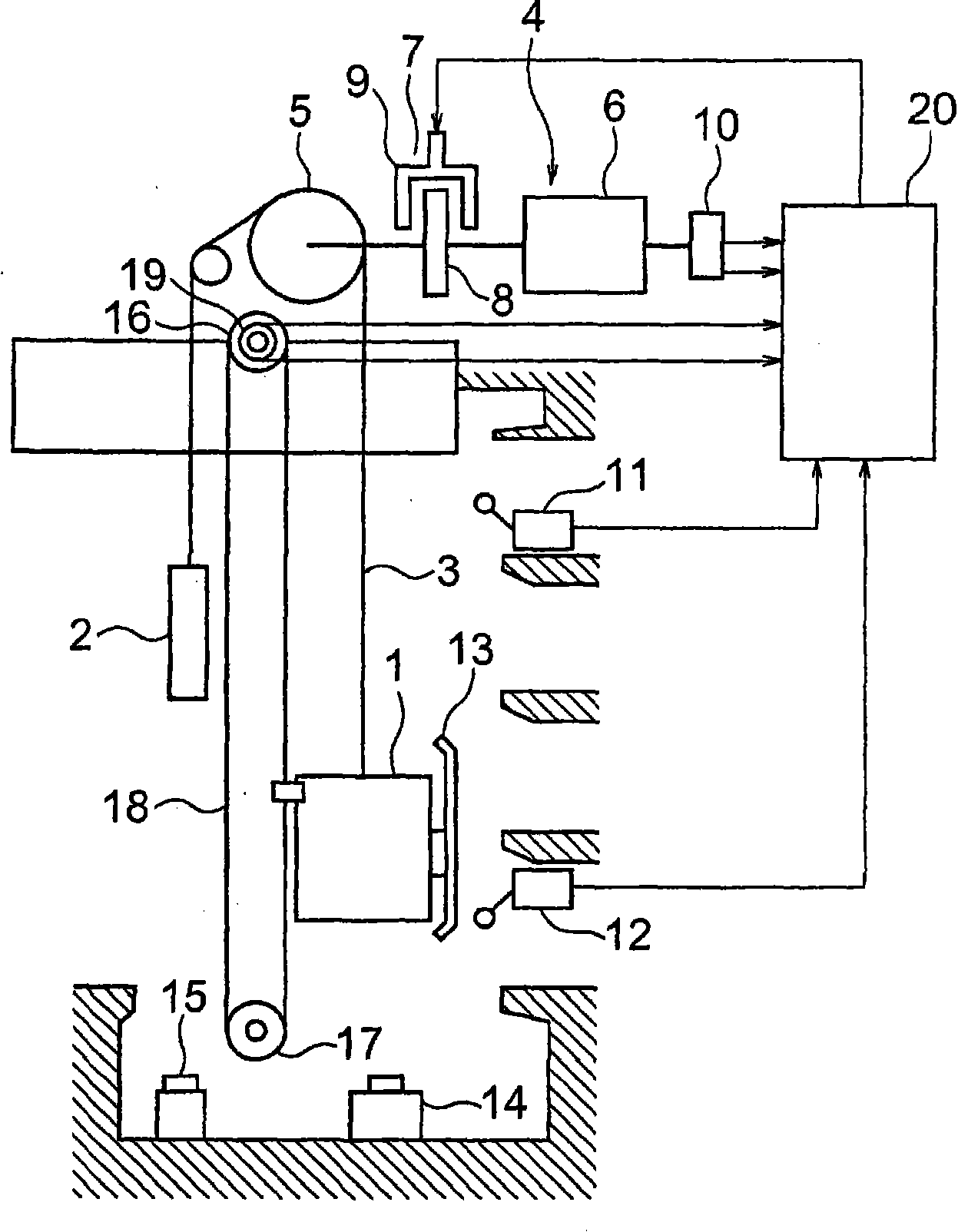
[0021] figure 1 It is a block diagram showing the elevator apparatus according to Embodiment 1 of the present invention. In the figure, the car 1 and the counterweight 2 are suspended in the hoistway by the main rope 3 as the suspension unit, and are lifted and lowered in the hoistway by the driving force of the traction machine 4 .

[0022] The hoisting machine 4 has a driving sheave 5 for winding the main rope 3 , a hoisting machine motor 6 for rotating the driving sheave 5 , and a braking device 7 for braking the rotation of the driving sheave 5 . The braking device 7 has: a brake drum (brake wheel) 8 coaxially engaged with the drive sheave 5; a brake shoe 9 that contacts / separates from the brake drum; the brake shoe 9 is pressed against the brake drum 8 And apply the brake spring of braking force; And electromagnet, it overcomes brake spring and makes brake shoe 9 leave brake drum 8, and releases braking force.

[0023] The hoisting machine motor 6 is provided with a hoi...

Embodiment approach 2

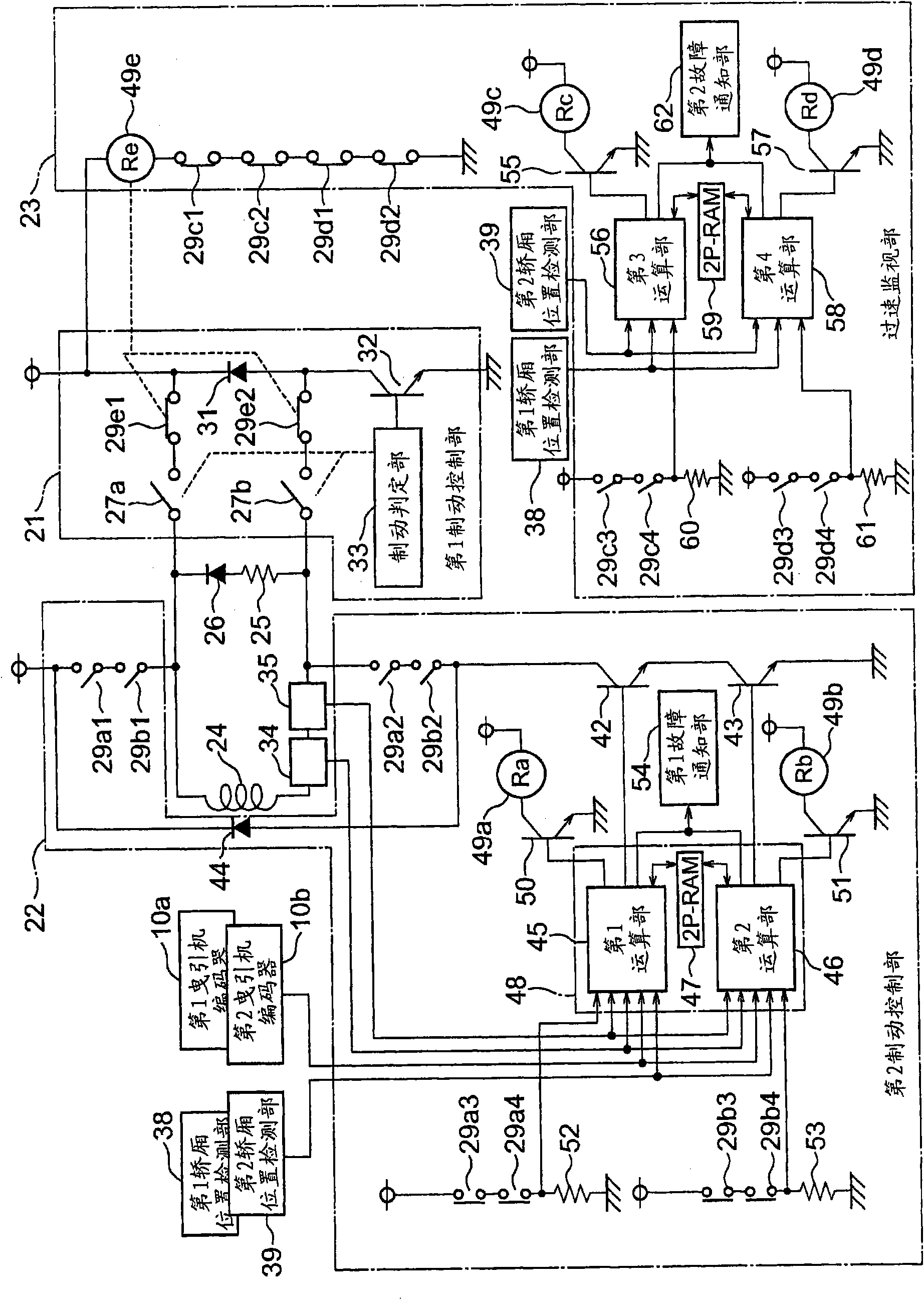
[0094] under, Figure 8 It is a circuit diagram showing the braking control device of the elevator apparatus according to Embodiment 2 of the present invention. In this example, the function of the third computing unit 56 in the first embodiment is integrated into the first computing unit 45 , and the function of the fourth computing unit 58 in the first embodiment is integrated in the second computing unit 46 .

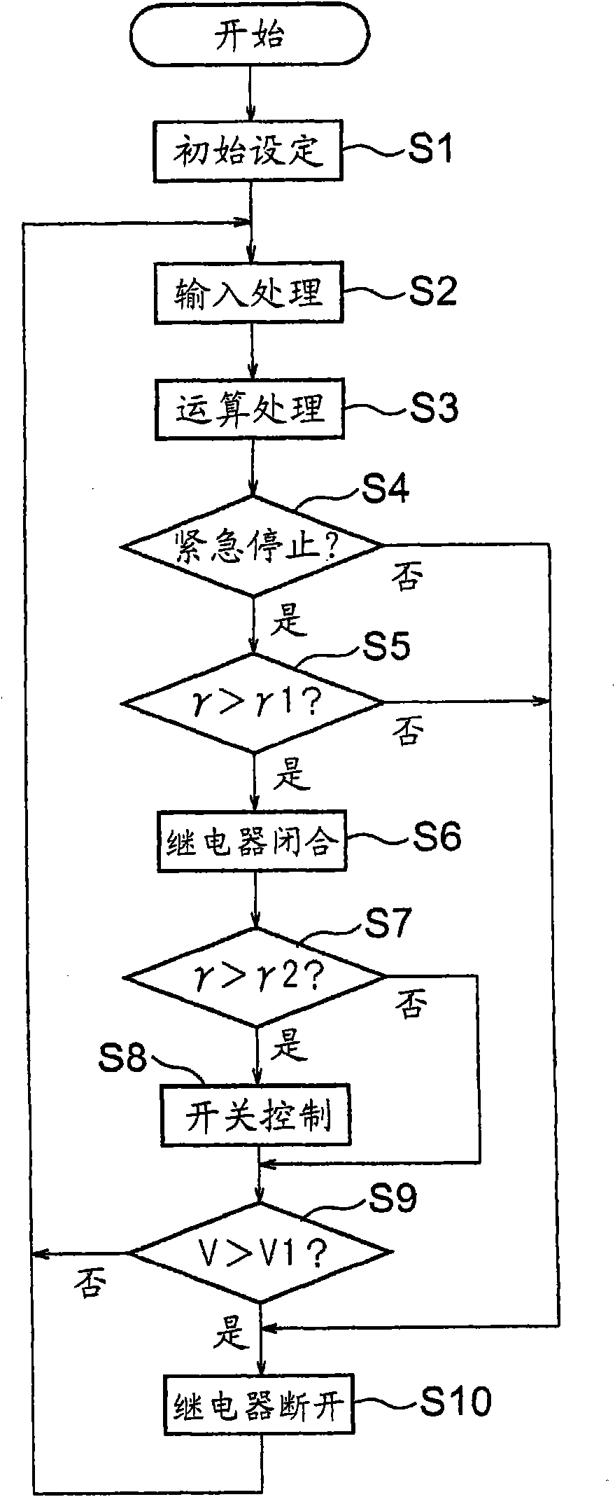
[0095] and, Figure 9 yes means Figure 8 The flow chart of the operation of the first and second computing units 45 and 46 in FIG. The first and second computing units 45 and 46 repeatedly execute failure detection processing (step S14 ), overspeed detection processing (step S15 ), and brake control processing (step S16 ) at predetermined cycles. In addition, the first and second computing units 45 and 46 sequentially execute the above-mentioned processing one by one as a single task. Other structures are the same as those in Embodiment 1.

[0096] According to s...

Embodiment approach 3

[0098] under, Figure 10 It is a circuit diagram showing a brake control device for an elevator apparatus according to Embodiment 3 of the present invention. In this example, input and output signals to the first and second computing units 45 and 46 in the circuit configuration as in the second embodiment are integrated and processed using a plurality of interfaces.

[0099] In the figure, the first and second computing parts 45, 46, dual-port RAM 47, failure notification part 54, input interface 72, output interface 73, the first input connector 74, the first 2. Input connector 75, first output connector 76, second output connector 77, and first to fourth data buses 78 to 81.

[0100] Input signals from the outside of the multiplex operation unit 71 are input to the input interface 72 through the first and second input connectors 74, 75, are distributed to the first and second data buses 78, 79 at the input interface 72, and are input to the first and the second computing u...


PUM


Abstract

In an elevator apparatus, a brake control device comprises a first brake controller for operating a braking device to bring a cage to an emergency stop when an abnormality is detected and a second brake controller for reducing braking force of the braking device when the deceleration of the cage reaches a threshold value or more during the emergency braking operation of the first brake controller. The second brake controller includes a first and a second computation unit for performing the operation of reducing the braking force of the braking device by computation processing independently ofeach other, the threshold value is set in the first computation unit so as to vary according to the cage position, and the threshold value is set in the second computation unit in the same manner as in the first computation unit.

Description

technical field [0001] The present invention relates to an elevator apparatus provided with a brake control device capable of controlling deceleration of a car during emergency braking. Background technique [0002] In a conventional braking device for an elevator, the braking force of the electromagnetic brake is controlled according to a deceleration command value and a speed signal during emergency braking so that the deceleration of the car reaches a predetermined value (for example, refer to Patent Document 1). [0003] In addition, in the conventional elevator apparatus, when the car travels toward the terminal floor near the terminal floor after the emergency stop command is issued, the car decelerates rapidly with a large deceleration and stops. Furthermore, when an emergency stop command is issued, unless the car is traveling toward the terminal floor near the terminal floor, the car decelerates at a sufficiently small deceleration and stops (for example, refer to P...

Claims


Application Information

Patent Timeline
Patent Type & Authority Applications(China)
IPC IPC(8): B66B1/32
CPCB66B1/32B66B5/02B66B1/24B66B1/30B66B5/04
Inventor 上田隆美
Owner MITSUBISHI ELECTRIC CORP
Why Eureka
Try Eureka