Method for producing planar type light-emitting display panels
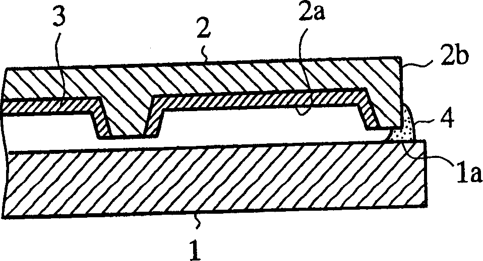
A technology of light-emitting display and manufacturing method, which is applied in the manufacture of discharge tubes/lamps, cold cathode manufacture, electrode system manufacture, etc., can solve the problem that the fluidity of sintered glass 4 is reduced, the sintered glass 4 penetrates into the display unit, and cannot flow to the needle sufficiently. Electrode etc.
- Summary
- Abstract
- Description
- Claims
- Application Information
AI Technical Summary
Problems solved by technology
Method used
Image

Examples
Embodiment 1
[0052] Figure 4 It is a plan view for explaining the first half steps of the display panel manufacturing method in Embodiment 1 of the present invention, Figure 5 for Figure 4 The V-V line profile, Figure 6 It is a plan view used to illustrate the second half of the steps in the display panel manufacturing method of Embodiment 1 of the present invention, Figure 7 for Figure 6 Sectional view of line VII-VII, Figure 8 It is an enlarged cross-sectional view for explaining the step of coating the needle electrodes with sintered glass in the display panel manufacturing method according to the first embodiment of the present invention. In addition, the components of Embodiment 1 neutralize Figure 1 to Figure 3 Components of the display panels of the previously filed patents shown in FIG.
[0053] The symbol 6 in the figure is the needle electrode installed on the electrode part of the front panel 1, the symbol 7 is a through slit hole, which is formed on the back panel...
Embodiment 2
[0063] Figure 9 It is a plan view for explaining the steps of the manufacturing method of the display panel of the second embodiment of the present invention, Figure 10 for Figure 9 The X-X line profile. In addition, the components of the second embodiment that are the same as those of the first embodiment are denoted by the same symbols, and descriptions of these components are omitted.
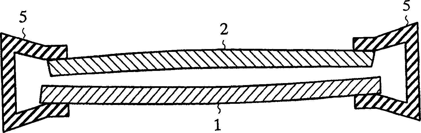
[0064] The second embodiment is characterized in that several coil springs (pressing means) 15 are disposed between the back panel 2 and the pressing plate 11 at appropriate intervals, and these springs act in the direction of opening the interval between them. Utilizing the elastic force of this coil spring 15, it is pushed in the direction of expanding the distance between the back panel 2 and the pressing plate 11, so the front panel 1 and the back panel 2 can be evenly bonded by the stress of the pressing plate 11 on the back panel 2. .
[0065] In addition, in the second embodime...
Embodiment 3
[0066] In Embodiment 1 or Embodiment 2, after applying the fritted glass to the needle electrode 6, the fritted glass is applied to the side of the display panel, while the third embodiment is characterized in that the order of applying the fritted glass is reversed. . That is, in Example 3, in the state where the two boards 1, 2 are uniformly pressed on the whole surface, the fritted glass is coated on the side of the board, dried to temporarily fix the two boards 1, 2, and then The needle electrode 6 is coated with sintered glass and sintered.
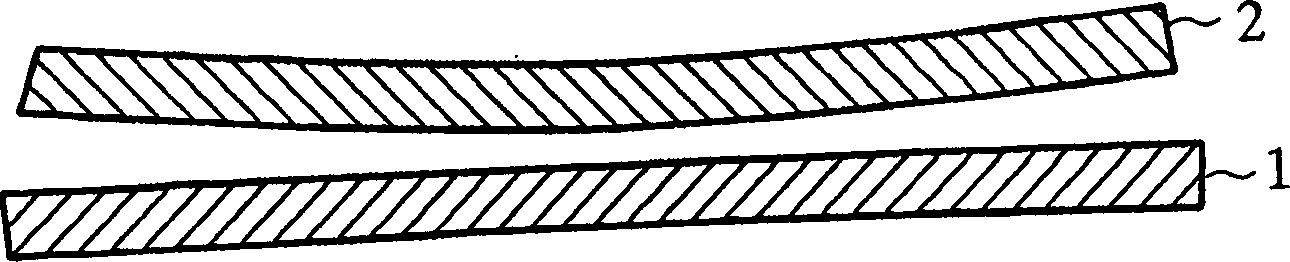
[0067] Embodiment 3 is the same as Embodiment 1 or Embodiment 2. The front panel 1 and the back panel 2 can be temporarily fixed under the condition that the two boards 1 and 2 are evenly pressed, so that the warping of the two boards can be prevented. A gap is formed between 1 and 2, thereby preventing frit glass 4 from penetrating into the gap between the panels.
[0068] Again, embodiment three is the same as embodiment one or emb...
PUM
 Abstract
Description
Claims
Application Information
 - R&D
- Intellectual Property
- Life Sciences
- Materials
- Tech Scout
- Unparalleled Data Quality
- Higher Quality Content
- 60% Fewer Hallucinations
Browse by: Latest US Patents, China's latest patents, Technical Efficacy Thesaurus, Application Domain, Technology Topic, Popular Technical Reports.
© 2025 PatSnap. All rights reserved.Legal|Privacy policy|Modern Slavery Act Transparency Statement|Sitemap|About US| Contact US: help@patsnap.com