Analog electronic timer

A technology of electronic timer and count value, applied in instruments, electrical components, electric winding, etc., can solve problems such as high-speed driving difficulties

Inactive Publication Date: 2003-01-15
SEIKO INSTR INC
View PDF0 Cites 7 Cited by
  • Summary
  • Abstract
  • Description
  • Claims
  • Application Information

AI Technical Summary

Problems solved by technology

Therefore, since driving with the correction drive pulse is frequently performed when driving the motor with the normal drive pulse repeatedly fails, there arises a problem that it becomes difficult to realize high-speed drive due to a long drive cycle of the motor.

Method used


Image

  • Analog electronic timer
  • Analog electronic timer
  • Analog electronic timer

Examples


Embodiment Construction

[0021] Modes for carrying out the invention will now be described in detail with reference to the accompanying drawings.

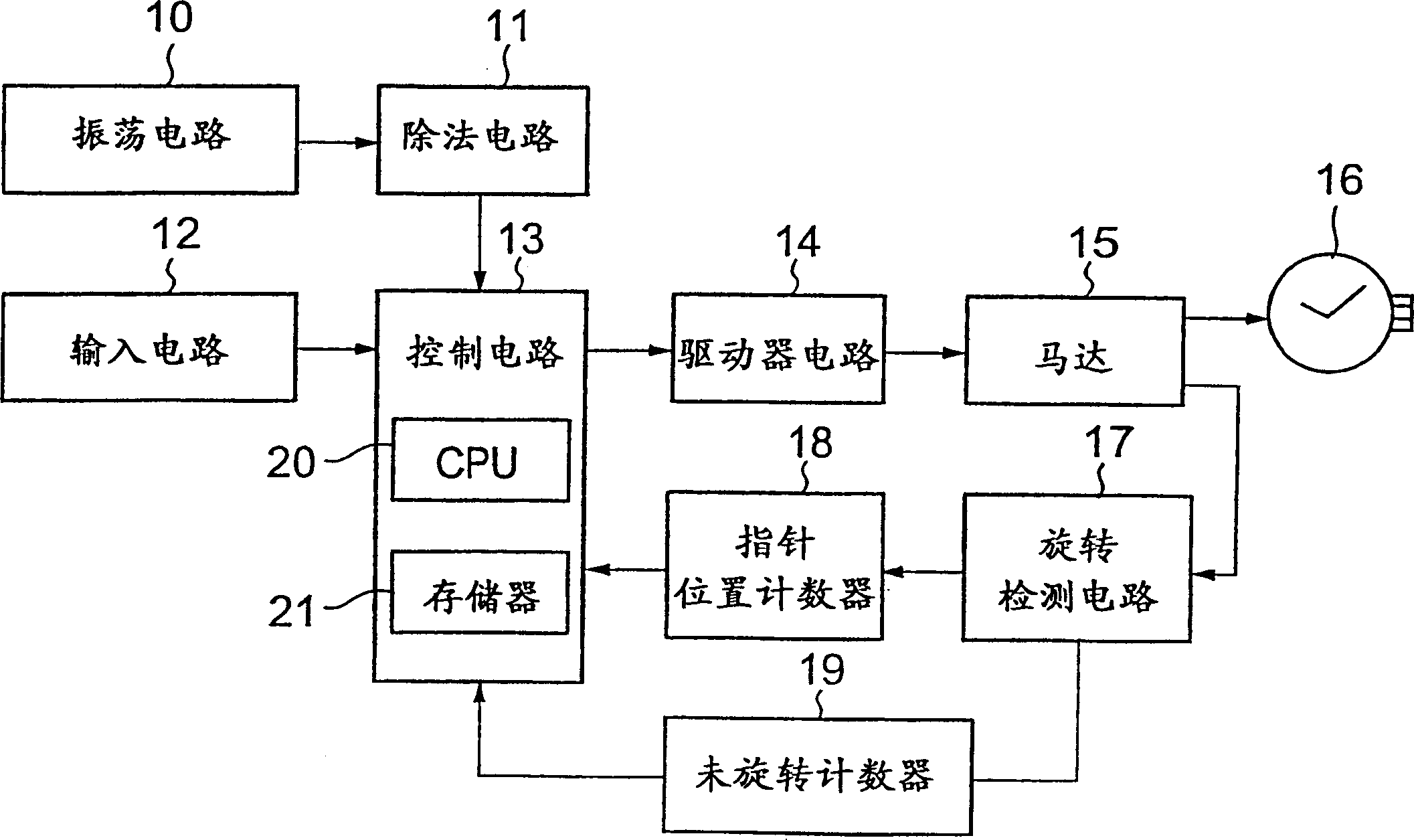
[0022] figure 1 is a block diagram of an analog electronic timepiece according to a mode for realizing the present invention, and it illustrates an example of an analog electronic wristwatch.

[0023] exist figure 1 Among them, the oscillation circuit 10 is connected to the first input portion of the control circuit 13 through the division circuit 11 . The input circuit 12 is connected to a second input portion of the control circuit 13 . The control circuit 13 has a central processing unit (CPU) 20 and a memory 21 constituted by ROM (Read Only Memory) or RAM (Random Access Memory). Processing programs are stored in the memory 21, and the CPU 20 performs processing by executing the programs, which will be described below. A count value representing the target position to which the pointer 16 is to be moved is stored in the memory 21 .

[0024] An outp...


PUM


Abstract

The object of the present invention is to make it possible to drive a motor at a high speed without causing any shift in the position of a hand. A memory stores a count value representing a target position to which a hand is to move; a rotation detecting circuit detects that a motor has rotated to output a rotation detection pulse signal and detects that the motor has not rotated to output a non-rotation detection pulse signal; a hand position counter counts the rotation detection pulse signal; and a control circuit controls the rotation of the motor with a normal pulse until the count value stored in the memory and the value counted by the hand position counter agree with each other. When a non-rotation counter counts a predetermined number of consecutive non-rotation detection pulse signals, the control circuit drives the motor with a corrective driving pulse having a great pulse width.

Description

technical field [0001] The present invention relates to an analog electronic timepiece, wherein a driving pulse supplied from a motor control device controls the rotation of a motor to drive hands, and wherein the hands are driven to rotate by the motor. technical background [0002] Analog electronic timepieces including chronographs have conventionally been used, in which a drive pulse supplied by a motor control device controls the rotation of a motor to drive hands, and in which the hands are driven to rotate by the motor. An analog electronic timepiece can be used in such a manner that a hand (second hand, clock or minute hand) is driven at high speed to move to a predetermined position. For example, the hands are driven at high speed in some cases, including the case where the second hand of the chronograph is returned to the zero hour position and the case where the hand is moved to a position indicating the current time after temporarily stopping the hand. In this c...

Claims


Application Information

Patent Timeline
Patent Type & Authority Applications(China)
IPC IPC(8): G04C3/14G04C9/08H02P8/02
CPCG04C3/14G04C3/143
Inventor 小笠原健治
Owner SEIKO INSTR INC
Why Eureka
Try Eureka