Plate loop heat pipe (I)

A flat-plate, loop technology, used in indirect heat exchangers, lighting and heating equipment, etc., can solve problems such as rising prices, reduced heat transfer, and large temperature differences

Inactive Publication Date: 2003-03-19
李嘉豪
View PDF0 Cites 30 Cited by
  • Summary
  • Abstract
  • Description
  • Claims
  • Application Information

AI Technical Summary

Problems solved by technology

[0005] When one end of the heat pipe 1 is heated and the liquid in the heat pipe evaporates, the vapor flows toward the condensation area and condenses into a liquid, and the liquid returns to the evaporation area through the capillary tissue. Since the fluid return circuit of the heat pipe is set in the same channel, the vapor will The flow directions of the liquid flow and the liquid flow conflict with each other in the channel, which reduces the heat transfer, and the remaining non-condens

Method used


Image

  • Plate loop heat pipe (I)
  • Plate loop heat pipe (I)
  • Plate loop heat pipe (I)

Examples


Embodiment Construction

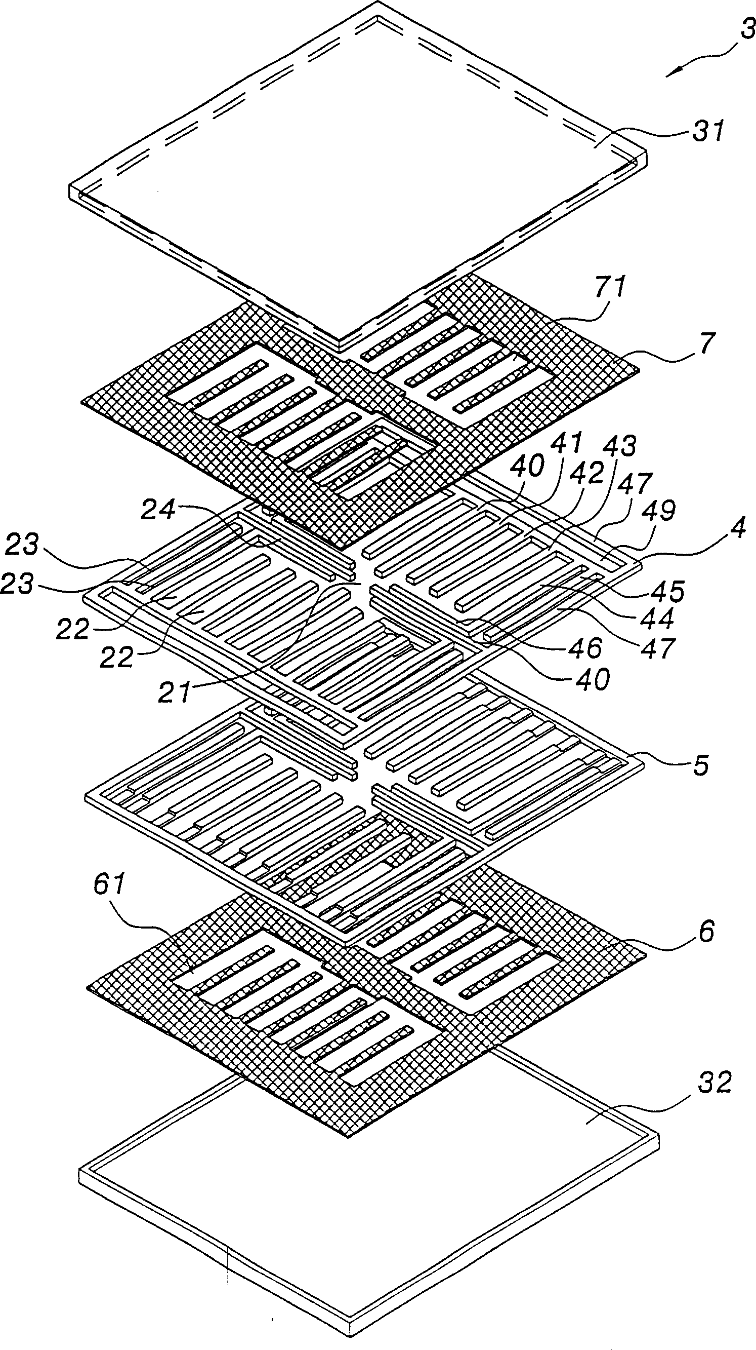
[0017] exist figure 2 , 3 , 4, 5, 6 and Figure 7 Among them, one embodiment of the present invention is a loop type heat pipe, which has a shell 3, which is a hollow closed body, and the shell 3 is filled with an appropriate amount of liquid. The filling amount of the liquid refers to the range from filling the capillary tissue that can appear and exist in the housing to filling up 80-90% of the volume of the passages in each circuit of the first annular circuit board in the circuit.

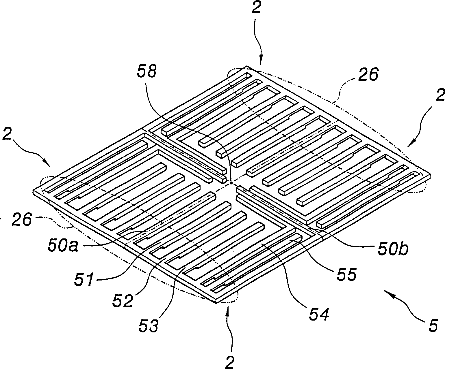
[0018] There is at least one hollow first annular circuit board 5 and at least one second annular circuit 4 which is hollow. The circuit board 4 is formed with at least one circuit 2 in the housing 3, and the circuit 2 is to form each channel with a hollow space, and the housing 3 is composed of a top case 31 and a bottom case 32, and the periphery of the top case 31 and the bottom case The peripheral edges of the bottom case 32 are joined together to form the casing 3 in an airtight manner...


PUM


Abstract

The plate loop heat pipe includes at least one annular loop plate inside a hollow casing to form at least one loop including successively connected evaporating area, steam channel, condensing area and fluid returning channel. Proper amount of fluid is filled inside the casing, the fluid returning channel is independent form the steam channel, the cover of the annular loop is provided with capillary structure, and the flow resistance of the steam channel is smaller than that of the fluid returning channel. The fluid is heated in the evaporating area, heat dissipated in the condensing area and made to flow stably in one direction, and thus the non-coagulating gas in the loop has less effect on the temperature homogeneity of the loop. The heat pipe has high heat homogeneity and large heat transferring amount.

Description

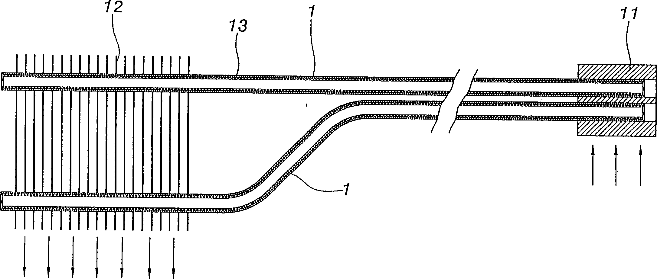
technical field [0001] The invention belongs to a flat plate loop heat pipe, in particular to a heat exchange structure with large heat transfer, good temperature uniformity, and little influence on the characteristics of the loop system for the non-condensable gas existing in the plate heat pipe. Background technique [0002] Existing heat pipes have been widely used in heat dissipation components of electronic components due to their relatively good heat transfer properties. Usually, heat pipe-type heat dissipation components have a heat pipe 1 and a heat conducting block 11 at the end of the electronic component. The heat conducting block 11 is connected to one end of the heat pipe 1, and the other end of the heat pipe 1 can be connected to the heat exchange device through another heat conducting block, or the other end of the heat pipe 1 is directly sandwiched with several cooling fins 12. figure 1 Shown in, namely is the heat pipe of radiating fin 12 formula. [0003] ...

Claims


Application Information

Patent Timeline
IPC IPC(8): F28D15/02
CPCF28D15/0233F28D15/0266
Inventor 李嘉豪
Owner 李嘉豪
Why Eureka
Try Eureka