Deflecting coil

A technology for installing deflection coils and coils, applied in the direction of electrode devices and related components, cathode ray tubes/electron beam tubes, discharge tubes, etc., can solve the problems of no deflection deformation, simple action of electron beams, and no description, etc.

Inactive Publication Date: 2003-03-19
KK TOSHIBA
View PDF1 Cites 0 Cited by
  • Summary
  • Abstract
  • Description
  • Claims
  • Application Information

AI Technical Summary

Problems solved by technology

However, in this publication, there is no description at all of using the aforementioned square coil separator, a square horizontal deflection coil is arranged inside the coil separator, and a vertical deflection coil directly wound on a circular magnetic core is provided outside the coil separator. Method for effectively correcting deflection distortion occurring in a deflection yoke device in the case of a structure of a deflection yoke
[0012] Especially relative to the square coil divider, the square horizontal deflection coil is set inside the coil divider, and the vertical deflection coil directly wound on the circular magnetic core is arranged outside the coil divider (relative to the square coil divider). The reason why the coil divider is not a square vertical deflection coil but a circular vertical deflection coil is to reduce the cost (cost reduction) of the structure. When correcting the deflection deformation that occurs by the deflection coil device, the The circular vertical deflection coil has no degree of freedom in the formation of the magnetic field, and has a simple effect on the electron beam, and has the problem that it cannot respond to various deflection deformation corrections.
[0013] As mentioned above, in the prior art, there is no means of correcting the deflection deformation of all shapes that cannot be corrected by the coil group, and in particular, there is no description about using a square-shaped coil divider and a square horizontal The method of correcting the deflection deformation that occurs by using a deflection yoke device composed of a combination of a deflection yoke and a vertical deflection yoke directly wound on a circular magnetic core.

Method used


Image

  • Deflecting coil
  • Deflecting coil
  • Deflecting coil

Examples


Embodiment Construction

[0042] Embodiment of the invention

[0043] Embodiments of the present invention will be described below with reference to the drawings.

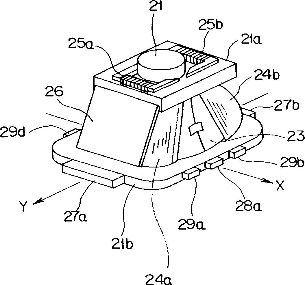
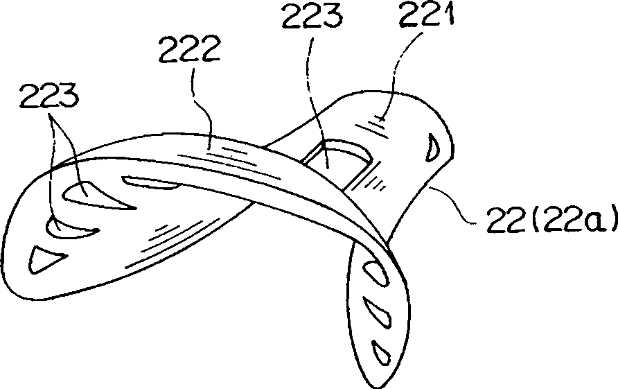
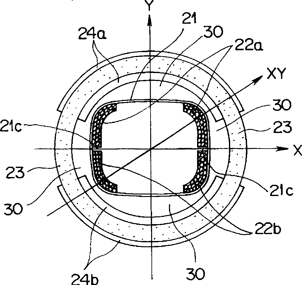
[0044] figure 1 It is a perspective view of a deflection yoke device according to an embodiment of the present invention. In the case of this embodiment, the cone shape of the CRT on which the deflection yoke device is installed is square, so that the saddle-shaped horizontal deflection coil installed on the deflection yoke device is also as figure 2 Shown square.

[0045] The coil spacer 21 made of an insulator has a square shape that gradually expands from the small-diameter portion on the neck side to the large-diameter portion on the front side, and a pair of horizontal deflection coils 22 ( figure 2 Only shows the coil 22a) of the half body in a pair of coils 22a, 22b, on the outer side is provided with a pair of horn-shaped vertical deflection coils 24 (24a, 24b) wound directly on the circular magnetic core 23 .

[0046] In ord...


PUM


Abstract

To provide a deflection yoke device which can correct deflection distortion, especially, screen distortion of lateral lines seen in a deflection yoke device constituted of a combination or the like of a square horizontal deflection coil and a vertical deflection coil directly wound around a round ferrite core. SOLUTION: In a deflection yoke device having a horizontal deflection coil 22 and a vertical deflection coil 24 arranged on a coil mounting frame 21 having a shape enlarging from a small diameter-portion to a large diameter-portion, there are provided a pair of magnets 27a, 27b which are arranged on the upper and lower ends of the large diameter portion of the coil mounting frame 21, having magnetic poles in the X direction, and right and left six magnets (28a, 28b, 29a to 29d) which are arranged equally at the right and left ends of the large diameter portion of the coil mounting frame 21, having magnetic poles in the Y direction for correcting lateral line distortion in the vicinity of the right and left ends in the upper and lower portions of a CRT screen. Six magnets on the right and left sides having magnetic poles in the Y direction consist of two magnets (28a, 28b) arranged on an X-axis to curve an electron beam toward the inside of the screen in the horizontal direction, and four magnets (29a to 29d) arranged on middle portions in a vertical direction to exert magnetic force to curve the electron beam toward the outside of the screen in the horizontal direction.

Description

technical field [0001] The present invention relates to a deflection yoke apparatus (deflection yoke apparatus) for effectively correcting deflection deformation (especially horizontal line deformation) appearing on the screen of a cathode ray tube. Background technique [0002] Currently, a cathode ray tube (hereinafter referred to as a CRT) or a liquid crystal display panel (LCD) is mainly used as a display device such as a television receiver. Among them, a display device using a CRT uses a deflector for deflecting electron beams from the CRT. [0003] Various improvements can be made to this deflection yoke device, and recently, a high-precision and easy-to-assemble deflection yoke has been developed. [0004] The conventional semi-troidal deflection yoke device is installed at the position transferred from the neck of the CRT to the cone (cone), and is divided into two parts by a pair of annular iron cores (a pair of segmented troidal Cores) are wound in a trumpet sha...

Claims


Application Information

Patent Timeline
Patent Type & Authority Applications(China)
IPC IPC(8): H01J29/76
CPCH01J29/76H01J2229/5681H01J2229/7033
Inventor 城雄作中村和敏
Owner KK TOSHIBA
Why Eureka
Try Eureka