Rotary control circuit

A control circuit and controller technology, applied in fluid pressure actuators, earth movers/shovels, servo motors, etc., can solve problems such as body vibration of excavators

Inactive Publication Date: 2003-04-16
KOBELCO CONSTR MASCH CO LTD
View PDF0 Cites 12 Cited by
  • Summary
  • Abstract
  • Description
  • Claims
  • Application Information

AI Technical Summary

Problems solved by technology

For this reason, if the rotation is stopped su

Method used


Image

  • Rotary control circuit
  • Rotary control circuit
  • Rotary control circuit

Examples


no. 1 example

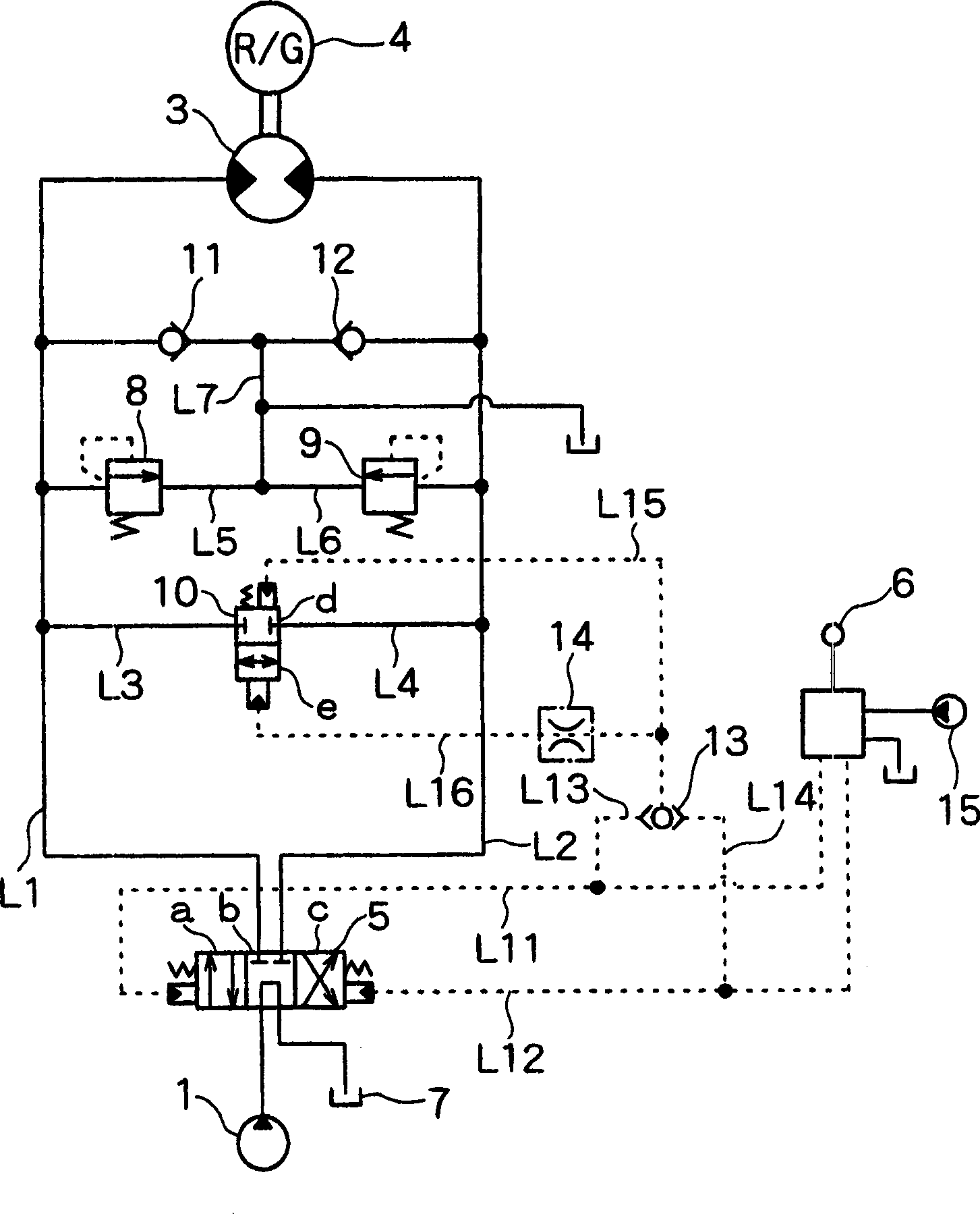
[0021] figure 1 is a schematic diagram of the rotation control circuit of the hydraulic excavator according to the first embodiment of the present invention. exist figure 1 In , the solid line represents the hydraulic pipe, and the dotted line represents the auxiliary pipe.

[0022] exist figure 1 Among them, through the control valve 5 as a directional control valve, the hydraulic pump 1 as a source of pressure oil and the hydraulic motor 3 that is rotationally driven by pressure oil such as the pressure oil output from the hydraulic pump 1 are connected to each other by using hydraulic pipes L1 and L2 together.

[0023] The hydraulic pump 1 is a variable displacement hydraulic pump, which is driven by an engine (not shown). Through the reduction mechanism 4, the hydraulic motor 3 rotates an upper rotating body (not shown) of the hydraulic excavator.

[0024] The control valve 5 is of the pressure assist valve type, which is adapted to be switched to any one of switch po...

no. 2 example

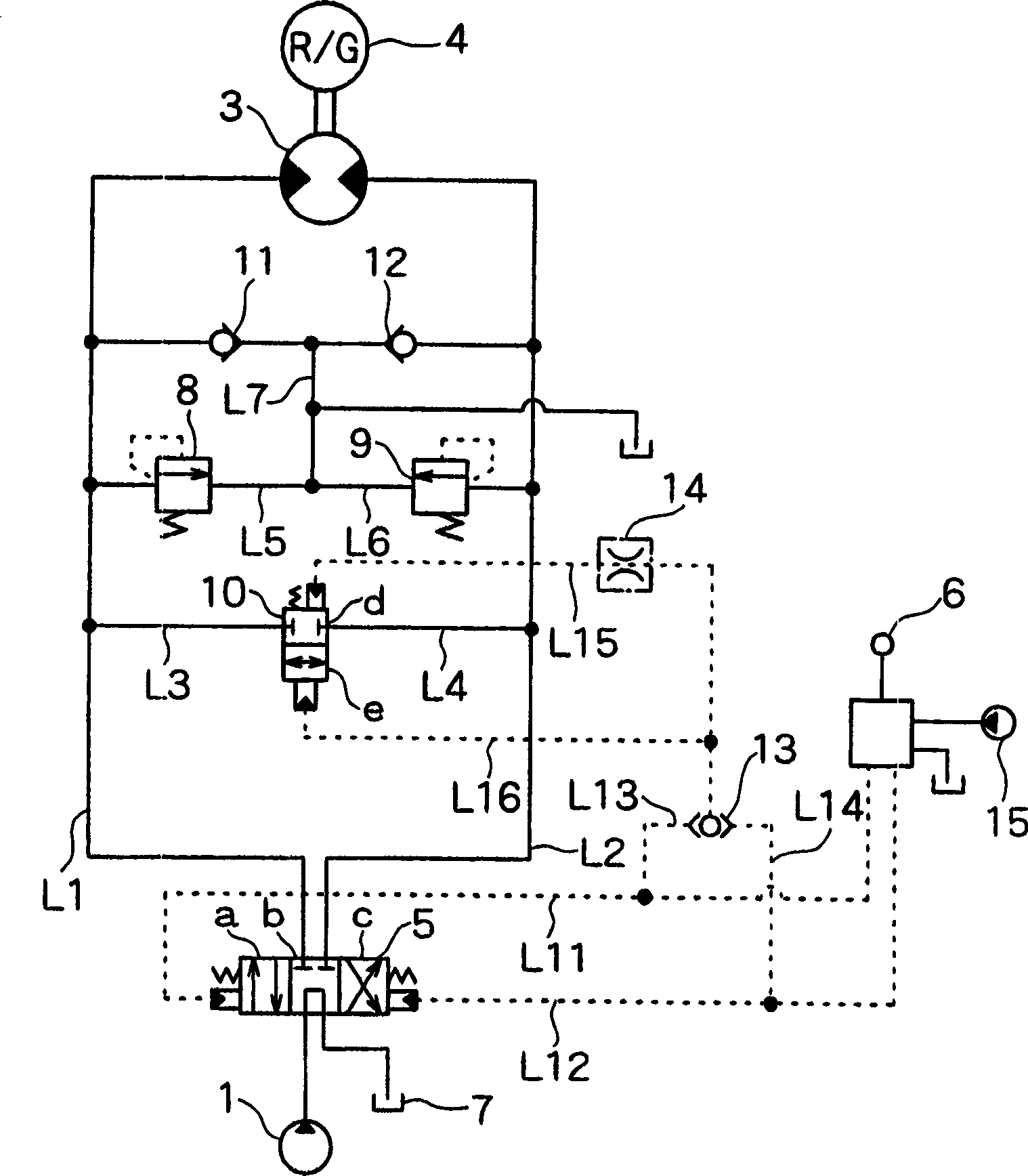
[0041] When the hydraulic excavator, especially the hydraulic excavator with a small turning radius of the tail, starts to rotate, it will cause its body to vibrate because of the same reason as described in the above-mentioned first embodiment. According to the second embodiment, it is possible to prevent the body from vibrating when starting to rotate.

[0042] figure 2 A schematic diagram showing a rotation control circuit of a hydraulic excavator according to a second embodiment of the present invention. exist figure 2 In this example, the throttle valve 14 as a controller is not provided in the auxiliary pipe L16 of the communication valve 10, but is provided in the auxiliary pipe L15. The other configurations are exactly the same as those of the first embodiment, and thus their descriptions are omitted.

[0043] exist figure 2 In , because the remote control valve 6 is in the middle position, the auxiliary pipes L11 and L12 are not under pressure. For this reason...


PUM


Abstract

The present invention comprises: a hydraulic motor rotationally driven as pressure oil from a hydraulic pump is supplied by way of a control valve; a remote control valve adapted to switch the control valve; a bypath line connected to both hydraulic lines of the hydraulic motor; a communicating valve having a position for closing the bypath line and a position for opening the bypath line; and a throttle valve for controlling the communicating valve, wherein the throttle valve is adapted to set the communicating valve to a closed position at the time when said remote control valve is operated for rotating, and to set the communicating valve to an open position at the time when said remote control valve is returned to a neutral position, as well as to allow the pressure oil of deceleration side to be released by a predetermined time, whereby the flapping of the machine which may be caused such as at the time when the rotation is stopped in the hydraulic excavator can be avoided.

Description

field of invention [0001] The present invention relates to rotary control circuits, and more particularly, the present invention relates to rotary control circuits for construction machines. Background technique [0002] The hydraulic excavator, especially the hydraulic excavator with a small tail turning radius, has a small inertial force of the upper rotating body when it stops rotating. For this reason, if the rotation is stopped suddenly, the body of the excavator will vibrate. Also, when starting to spin, the body vibrates for the same reason. Contents of the invention [0003] An object of the present invention is to provide a rotation control circuit capable of avoiding body vibration when an upper rotating body of a construction machine or the like stops rotating. [0004] A construction machine according to the invention has a rotation control circuit for a working machine on which a rotating body is arranged, wherein the rotation control circuit includes: [0...

Claims


Application Information

Patent Timeline
IPC IPC(8): E02F9/20E02F9/22F15B11/00F15B11/08
CPCE02F9/2207E02F9/20
Inventor 但马一治
Owner KOBELCO CONSTR MASCH CO LTD
Why Eureka
Try Eureka