Rotary control circuit
A control circuit and controller technology, applied in fluid pressure actuators, earth movers/shovels, servo motors, etc., can solve problems such as body vibration of excavators
- Summary
- Abstract
- Description
- Claims
- Application Information
AI Technical Summary
Problems solved by technology
Method used
Image
Examples
no. 1 example
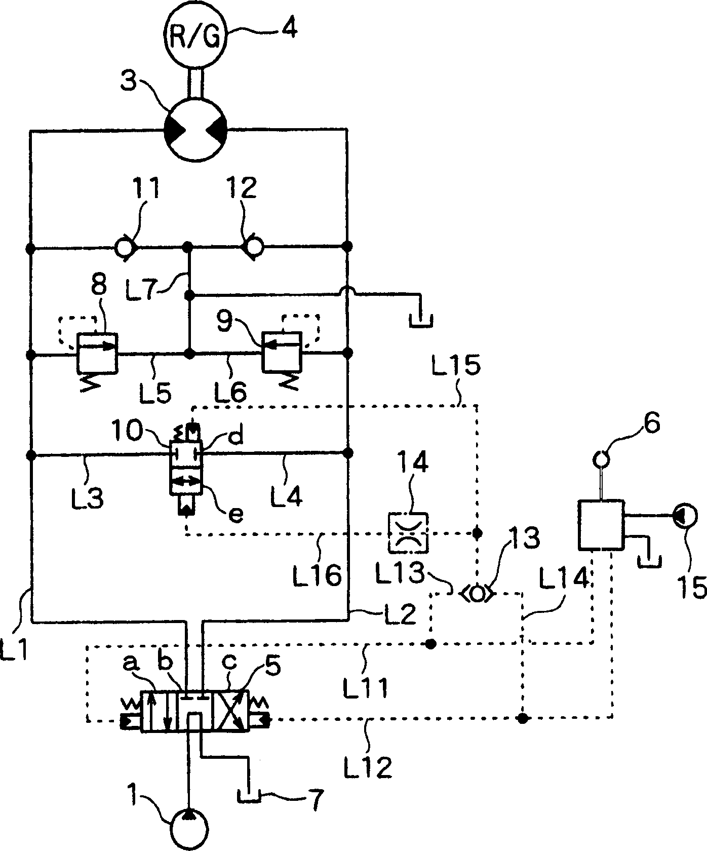
[0020] figure 1 is a schematic diagram of the rotation control circuit of the hydraulic excavator according to the first embodiment of the present invention. exist figure 1 In , the solid line represents the hydraulic pipe, and the dotted line represents the auxiliary pipe.
[0021] exist figure 1 Among them, through the control valve 5 as a directional control valve, the hydraulic pump 1 as a source of pressure oil and the hydraulic motor 3 that is rotationally driven by pressure oil such as the pressure oil output from the hydraulic pump 1 are connected to each other by using hydraulic pipes L1 and L2 together.
[0022] The hydraulic pump 1 is a variable displacement hydraulic pump, which is driven by an engine (not shown). Through the reduction mechanism 4, the hydraulic motor 3 rotates an upper rotating body (not shown) of the hydraulic excavator.
[0023] The control valve 5 is of the pressure assist valve type, which is adapted to be switched to any one of switch po...
no. 2 example
[0041] When the hydraulic excavator, especially the hydraulic excavator with a small turning radius of the tail, starts to rotate, it will cause its body to vibrate because of the same reason as described in the above-mentioned first embodiment. According to the second embodiment, it is possible to prevent the body from vibrating when starting to rotate.
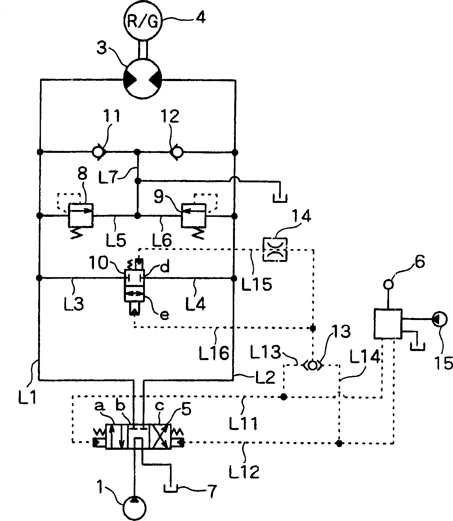
[0042] figure 2 A schematic diagram showing a rotation control circuit of a hydraulic excavator according to a second embodiment of the present invention. exist figure 2 In this example, the throttle valve 14 as a controller is not provided in the auxiliary pipe L16 of the communication valve 10, but is provided in the auxiliary pipe L15. The other configurations are exactly the same as those of the first embodiment, and thus their descriptions are omitted.
[0043] exist figure 2 In , because the remote control valve 6 is in the middle position, the auxiliary pipes L11 and L12 are not under pressure. For this reason...
PUM
 Abstract
Description
Claims
Application Information
 - R&D
- Intellectual Property
- Life Sciences
- Materials
- Tech Scout
- Unparalleled Data Quality
- Higher Quality Content
- 60% Fewer Hallucinations
Browse by: Latest US Patents, China's latest patents, Technical Efficacy Thesaurus, Application Domain, Technology Topic, Popular Technical Reports.
© 2025 PatSnap. All rights reserved.Legal|Privacy policy|Modern Slavery Act Transparency Statement|Sitemap|About US| Contact US: help@patsnap.com


