Fixed type constant-speed universal joint

A technology of constant velocity universal joints and internal components, which is applied to steering columns, steering controls installed on vehicles, and rotating parts that resist centrifugal force, etc., and can solve problems such as inability to rotate with freewheeling

Inactive Publication Date: 2003-04-30
NTN CORP
View PDF0 Cites 10 Cited by
  • Summary
  • Abstract
  • Description
  • Claims
  • Application Information

AI Technical Summary

Problems solved by technology

As mentioned above, in the fixed type constant velocity universal joint, the track clearance is indispensable, so it is inevitable to produce more than a certain degree of lost motion, and this fixed type constant velocity universal joint cannot be used for example For applications where it is not expected to turn around freely, such as the steering device of a car

Method used


Image

  • Fixed type constant-speed universal joint
  • Fixed type constant-speed universal joint
  • Fixed type constant-speed universal joint

Examples


Embodiment Construction

[0030] Below, according to Figure 1 to Figure 13 Embodiments of the present invention will be described.

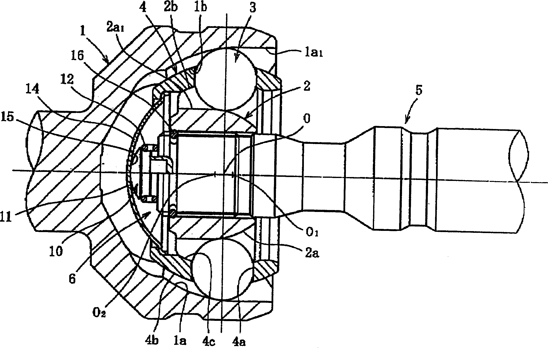
[0031] Figure 1 to Figure 12 A case where the present invention is applied to an undercut type (UJ) which is a fixed type constant velocity universal joint is shown as an example.

[0032] like figure 1 As shown, the main structural elements of this type of constant velocity universal joint include: an outer wheel 1 as an outer member equipped with a spherical inner surface 1b forming a plurality of rail grooves 1a, and an outer wheel 1 equipped with a spherical outer surface 2b forming a plurality of rail grooves 2a Inner wheel 2, a plurality of balls 3 arranged in the ball track formed by the cooperation of the rail groove 1a of the outer wheel 1 and the rail groove 2a of the inner wheel 2 are arranged on the spherical inner surface 1b of the outer wheel 1 and the spherical outer surface of the inner wheel 2 The cages 4 between 2b have pockets for receiving balls 3...


PUM


Abstract

A cage (4) is placed between the spherical inner surface (1b) of an outer unit (1) and the spherical outer surface (2b) of an inner unit (6). The cage has a pressing portion (11) which applies elastic pressing force to a receiving portion (15) in the axial direction. Either the pressing portion or receiving portion is provided on the cage and on the inner unit.

Description

technical field [0001] The present invention relates to a fixed type constant velocity universal joint, and a steering device having the same, and in particular to a fixed constant velocity universal joint suitable for applications in which spinning lost motion is not desired. Background technique [0002] Constant velocity universal joints are roughly divided into fixed types that allow only angular displacement between the input and output shafts, and sliding properties that allow angular and axial displacements, and models are selected according to various applications and conditions of use. [0003] As fixed type constant velocity universal joints, Zeppelin type (hereinafter referred to as "BJ") and unundercut type (hereinafter referred to as "UJ") are known. [0004] Both BJ and UJ are composed of an outer wheel with multiple curved track grooves on the inner periphery, an inner wheel with multiple curved track grooves on the outer periphery, balls assembled between the...

Claims


Application Information

Patent Timeline
Patent Type & Authority Applications(China)
IPC IPC(8): B62D1/19F16D3/22F16D3/2237F16D3/2245
CPCF16D2003/2232Y10S464/906F16D3/2237
Inventor 山崎健太五十公野纯一寺田健二藏久昭
Owner NTN CORP
Why Eureka
Try Eureka