Synchronizer used for speed change mechanism

一种同步装置、变速机的技术,应用在机械设备、机械驱动离合器、离合器等方向,达到提高操作感的效果

Inactive Publication Date: 2011-04-27
KYOWA METAL WORKS
View PDF2 Cites 10 Cited by
  • Summary
  • Abstract
  • Description
  • Claims
  • Application Information

AI Technical Summary

Problems solved by technology

[0013] The problem to be solved is that if it is necessary to overcome the centrifugal force acting on the rod member in the operation after the synchronization is completed, it is impossible to avoid the uncomfortable feeling in the operation when driving at high speed

Method used


Image

  • Synchronizer used for speed change mechanism
  • Synchronizer used for speed change mechanism
  • Synchronizer used for speed change mechanism

Examples


Embodiment 1

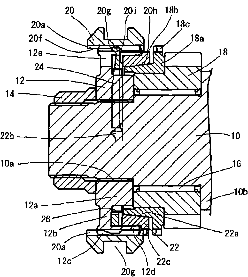
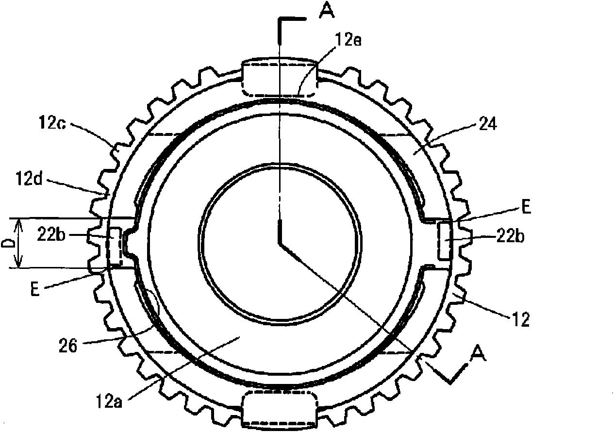
[0028] figure 1 It is a cross-sectional view of the main part of 1 embodiment of the device of the present invention, and is the same as figure 2 The cross-section of the part corresponding to the A-A line. figure 2 is removed figure 1 The output shaft 10, the 5th gear 18, and the synchronizer ring 22 on the 5th gear side in the middle are viewed from the right side (the 5th gear 18 side).

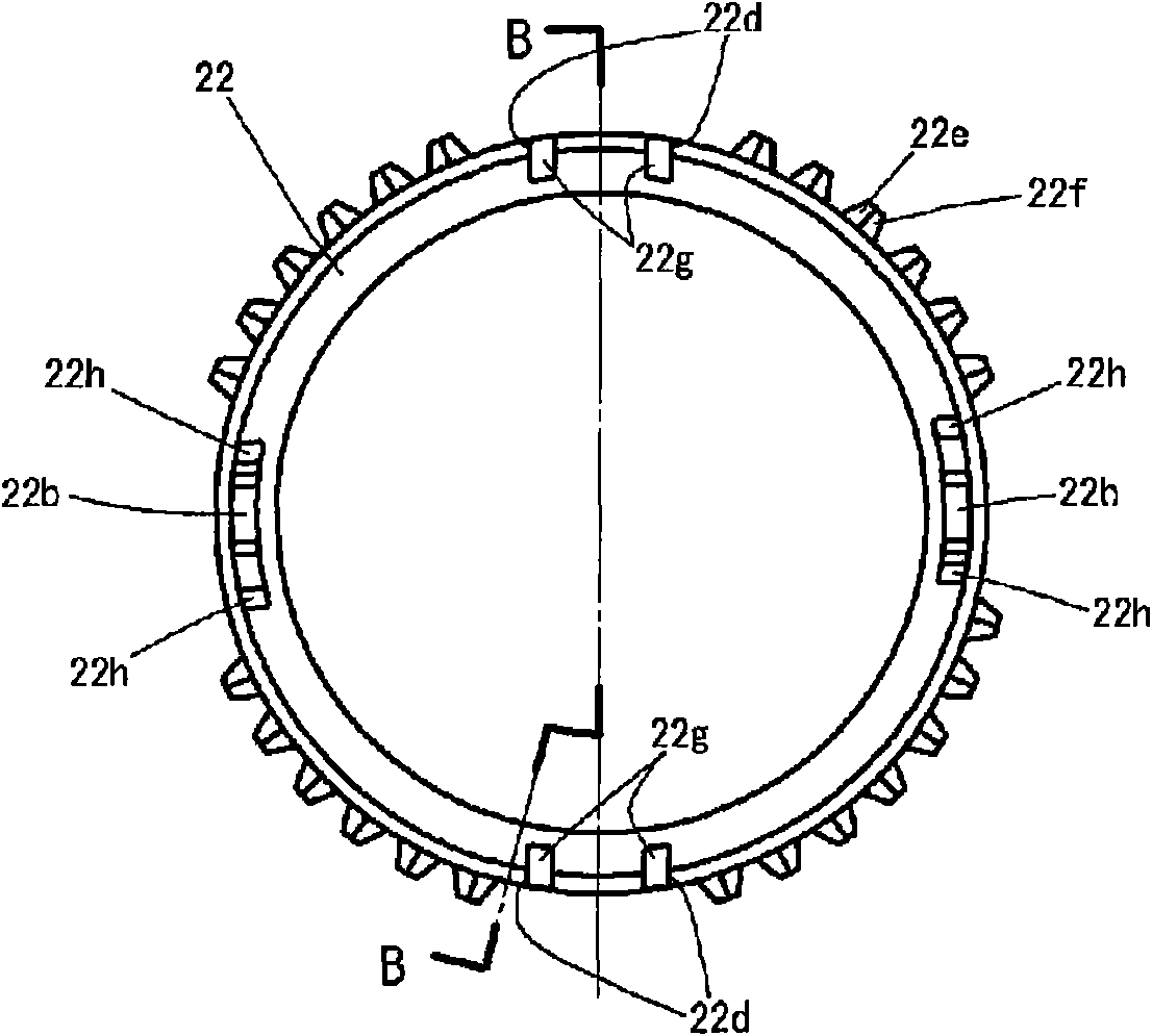
[0029] also, image 3 is the appearance of the synchro ring 22, from figure 1 See the figure on the left. and, Figure 4 express image 3 The section of the synchronizing ring at the line B-B.

[0030] and, Figure 5 is the appearance of the rod member 24, which is obtained from figure 1 See the figure on the left. and, Figure 6 express Figure 5 The section of the rod member 24 at the C-C line.

[0031] also, Figure 7 represents the cross-section of the sleeve 20, Figure 8 A partially enlarged section of the sleeve 20 is shown.

[0032] The output shaft 10 is connecte...


PUM


Abstract

The invention provides a synchronizer used for speed change mechanism. The synchronizer comprises a rod member having reverse gear noise preventing function and improving the speed change operation feel when shifting to, for example, the fifth gear in high speed driving. a rod member (24) is disposed among a shaft sleeve (12), a sleeve (20) and a synchronization ring (22); when the sleeve (20) moves the a change-speed gear (18), the synchronization ring (22) is compressed onto the change-speed gear (18) by the spline (22c) on the synchronization ring (22) to synchronize the two; when the sleeve (20) moves away from the a change-speed gear (18), the synchronization ring (22) is compressed to the change-speed gear (18) by the reverse turning effect of the rod member (24) to synchronize the two; the abutting of the high speed gear inclined plane (20g) of the sleeve and the top (24a) of the rod member (24) is released when the sleeve (20) is pressed onto the spline (22c) of the synchronization ring (22) directly.

Description

technical field [0001] The present invention relates to a synchronizer capable of transmitting, to a synchronizer ring, a pressing force directed toward a sleeve opposite to a high-speed transmission gear by utilizing a reverse action of a lever member during shift operation (gear switching) of a vehicle transmission. Background technique [0002] In the past, as this kind of synchronizing device for a transmission, a rod member is provided between the synchronizing ring and the bushing that can be pressure-contacted to the fifth-speed transmission gear. The turning action transmits the pressing force of the sleeve in the direction opposite to the 5th speed transmission gear to the synchronizer ring, and by pressing the sleeve against the 5th speed transmission gear, the sleeve is synchronized with the 5th speed transmission gear. After the rotation caused by the inertia of the clutch disc, it meshes with the reverse (reverse gear) gear. [0003] Such a simple structure can...

Claims


Application Information

Patent Timeline
Patent Type & Authority Applications(China)
IPC IPC(8): F16D23/04
CPCF16D2023/0637F16D2023/0656F16D23/025F16D2023/0631F16D23/0612Y10T74/19284
Inventor 平岩一美
Owner KYOWA METAL WORKS
Why Eureka
Try Eureka