Rotary input device and electronic equipment

A kind of input device and rotary technology, which is applied in the direction of measuring device, sub-office equipment, data processing input/output process, etc., can solve the problem of not being able to bring sense of operation

Inactive Publication Date: 2010-10-27
FUNAI ELECTRIC CO LTD +1
View PDF2 Cites 10 Cited by
  • Summary
  • Abstract
  • Description
  • Claims
  • Application Information

AI Technical Summary

Problems solved by technology

[0008] However, according to the rotary input devices described in Patent Documents 1 and 2, although the operator can give the operator a feeling of boosting and braking, it cannot provide the operation feeling (click feeling) obtained when the button is pressed mechanically. For operators with obvious and more obvious sense of operation, it cannot meet the demand

Method used


Image

  • Rotary input device and electronic equipment
  • Rotary input device and electronic equipment
  • Rotary input device and electronic equipment

Examples


Embodiment Construction

[0058] Hereinafter, embodiments of the present invention will be described in detail with reference to the drawings. In addition, the scope of the present invention is not limited to the illustrations.

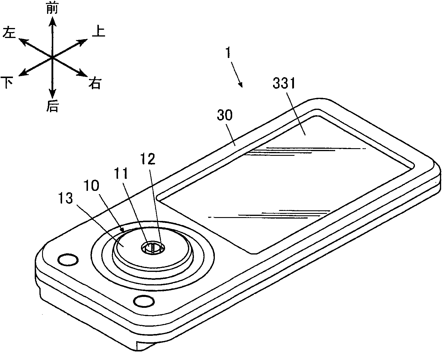
[0059] In this embodiment, as an electronic device including the rotary input device of the present invention, a mobile phone that performs voice calls through wireless communication will be described as an example.

[0060] In addition, in the following description, in the mobile phone 1 according to the present embodiment, the side where the rotary input device 10 and the display panel 331 of the display unit 33 are arranged is the front side, and the side where the rotary input device is arranged is regarded as the front side. 10 and the side opposite to one side of the display panel 331 serves as the rear side. Also, let the side where the display panel 331 is placed be the upper side, the side where the rotary input device 10 is placed is the lower side, and the directio...


PUM


Abstract

Disclosed is a rotary input device including: a rotary operation device; a detection section; a display control section; a rotation driving section to apply a rotary force to the rotary operation device; a first force sense presenting section to present a first force sense by a combination of at least any two of applying a rotary force in a normal rotation direction, applying a rotary force in a reverse rotation direction, and stopping applying when the detected rotation angle reaches a predetermined switching angle corresponding to the displayed predetermined display information; a second force sense presenting section to present a second force sense different from the first force sense by applying the rotary force in the normal rotation direction when the rotation angle detected by the detection section is within a first range, and in the reverse rotation direction when the angle is within a second range.

Description

technical field [0001] The present invention relates to a rotary input device and an electronic device having the rotary input device. Background technique [0002] In the past, such a rotary input device is known: as an operation input device for operating an electronic device, there is a rotary operating element such as a touch dial (dial), and the operator performs a rotating operation on the rotary operating element, thereby being able to change from the display to the display. Select a desired selection item etc. from a plurality of selection items on the upper part. [0003] Specifically, in this type of rotary input device, each time the rotation angle of the rotary operation element reaches the switching angle by the rotation operation, the selection items being selected are switched in a prescribed order, and the operator selects the desired After the selected item is switched to the selected state, the selection is determined by pressing the rotary operation eleme...

Claims


Application Information

Patent Timeline
Patent Type & Authority Applications(China)
IPC IPC(8): G06F3/01G06F3/033H04M1/02G06F3/0362G06F3/0489
CPCG06F3/016H04M1/026G06F3/0362G01C21/3664G01C21/265
Inventor 长岛贤治坪田浩乃高桥和浩铃木孝彦佐古伸行小平刚志
Owner FUNAI ELECTRIC CO LTD
Why Eureka
Try Eureka