Optimum scanning method for change coefficient in coding/decoding image and video

An encoding and double-scanning technology, which is applied in the field of encoding/decoding image signals, can solve the problems of reducing encoding efficiency, increasing the number of decoder bits, and data word length, etc.

Inactive Publication Date: 2003-07-23
SAMSUNG ELECTRONICS CO LTD
View PDF2 Cites 37 Cited by
  • Summary
  • Abstract
  • Description
  • Claims
  • Application Information

AI Technical Summary

Problems solved by technology

[0004] Zigzag scan patterns and predefined scan patterns are not effective on encoding all image signals
Also, since the information about the selected scan mode should be encoded with the image signal and provided to the decoder, the number of bits sent to the decoder increases.
Also, the scan pattern for `678 is predefined, so there is a limitation in choosing the best scan pattern for various decoded blocks
[0005] The scan pattern described in US Patent No. 6,263,026 has the problem of reducing the coding efficiency because if there are too many scan patterns one selected data word becomes too long
Also, the predefined limited scan patterns used in `026 are not valid in all images or data

Method used


Image

  • Optimum scanning method for change coefficient in coding/decoding image and video
  • Optimum scanning method for change coefficient in coding/decoding image and video
  • Optimum scanning method for change coefficient in coding/decoding image and video

Examples


Embodiment Construction

[0036] Reference must be made to the drawings, which illustrate a preferred embodiment of the invention, and to what is written on the drawings, in order to gain a full understanding of the invention, the advantages of its operation, and the objects accomplished by its operation.

[0037] Hereinafter, the present invention will be described in detail by explaining preferred embodiments of the invention with reference to the accompanying drawings. The same reference numerals in the drawings denote the same components.

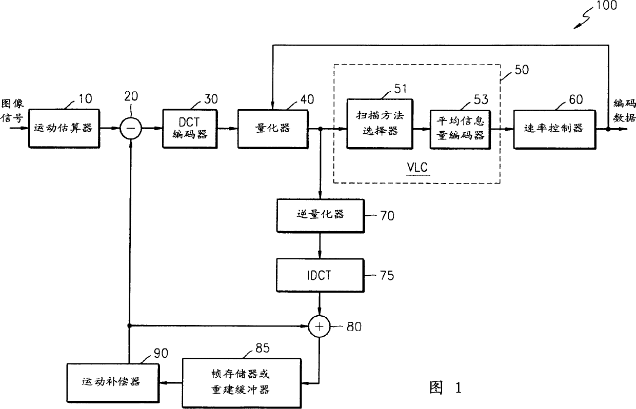
[0038] Figure 1 shows a block diagram of a general DCT coding system. Referring to Fig. 1, the DCT encoding system (or an encoder 100) includes a motion estimator 10, a subtractor 20, a DCT encoder 30, a quantizer 40, a variable length encoder 50, a rate controller 60 , an inverse quantizer 70 , an inverse DCT (IDCT) 75 , an adder 80 , a frame memory or reconstruction buffer 85 and a motion compensator 90 .

[0039] A variable length coder (hereinafter referre...


PUM


Abstract

The method involves selecting a reference block from a set of reference blocks. A scanning order to scan the blocks that is to be coded of the reference blocks is generated. The blocks to be coded are scanned in the order of the generated scanning order. The probabilities of the non-zero coefficients occurring from the selected reference block are obtained. The scanning order is determined in descending order.

Description

technical field [0001] The present invention relates to a method of encoding / decoding image signals, in particular, to an optimal scanning method for transform coefficients in encoding / decoding of images and videos. Background technique [0002] An image signal, such as an image or video, is passed through a discrete cosine transform (hereinafter referred to as "DCT") according to the Motion Picture Experts Group Phase 1 (MPEG-1), MPEG-2, MPEG-4, H.261, H.263 or JPEG compression or encoding. Also, the compressed or encoded image signal is decoded by inverse discrete cosine transform (hereinafter referred to as "IDCT"). Choosing an optimal scanning method is key when trying to improve encoding / decoding efficiency. [0003] The scan mode described in US Patent No. 5,500,678 improves coding efficiency and was chosen as the scan mode for MPEG-4 intra-coding. The scanning pattern of the `678 uses a zigzag scanning pattern and a predefined scanning pattern. [0004] Zigzag sca...

Claims


Application Information

Patent Timeline
Patent Type & Authority Applications(China)
IPC IPC(8): H04N7/24H03M7/30H04N1/41H04N19/129H04N19/134H04N19/136H04N19/196H04N19/60H04N19/625H04N19/91
CPCH04N19/00781H04N19/00278H04N19/00763H04N7/26244H04N7/26095H04N19/00775H04N19/00109H04N7/26122H04N7/50H04N19/00139H04N19/00024H04N7/30H04N7/34H04N7/26015H04N19/105H04N19/129H04N19/136H04N19/176H04N19/593H04N19/60H04N19/61H04N1/411H04N19/625H04N19/93
Inventor 李时和崔钟世
Owner SAMSUNG ELECTRONICS CO LTD
Why Eureka
Try Eureka