Switch device
Technology of a switchgear, connecting part, applied in the field of closed switchgear
- Summary
- Abstract
- Description
- Claims
- Application Information
AI Technical Summary
Problems solved by technology
Method used
Image

Examples
no. 1 example
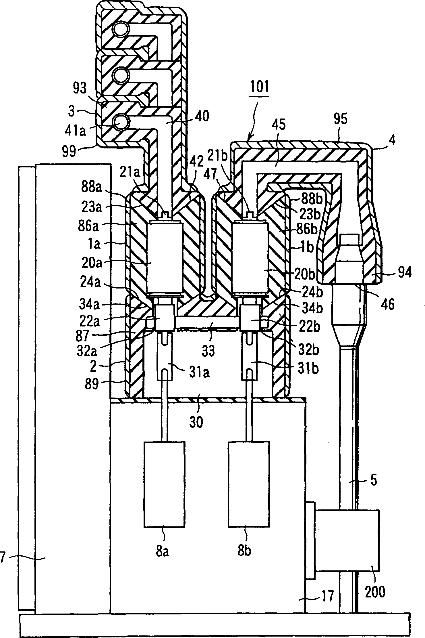
[0082] Figure 1 to Figure 4 are side sectional views showing first to fourth examples of the structure of the switchgear according to the present invention.
[0083] Figure 5 is a schematic diagram showing a first example of an electronic circuit C1 constituted by a switching device according to the present invention.
[0084] figure 1 The switching device 101 is constructed in Figure 5 Enclosed switchgear for electronic circuits shown in .
[0085] A major circuit portion of the switchgear 101 is covered by a thermosetting solid insulator such as epoxy.
[0086] The switchgear 101 is constructed by connecting a plurality of components (eg, solid insulating devices or solid molded devices) together in a vertical direction.
[0087] Each assembly includes: a number of pieces of switchgear constituting equipment (such as parts for switching operations); an insulating part that insulates parts of the switchgear constituting equipment; a connecting part that can verticall...
no. 2 example
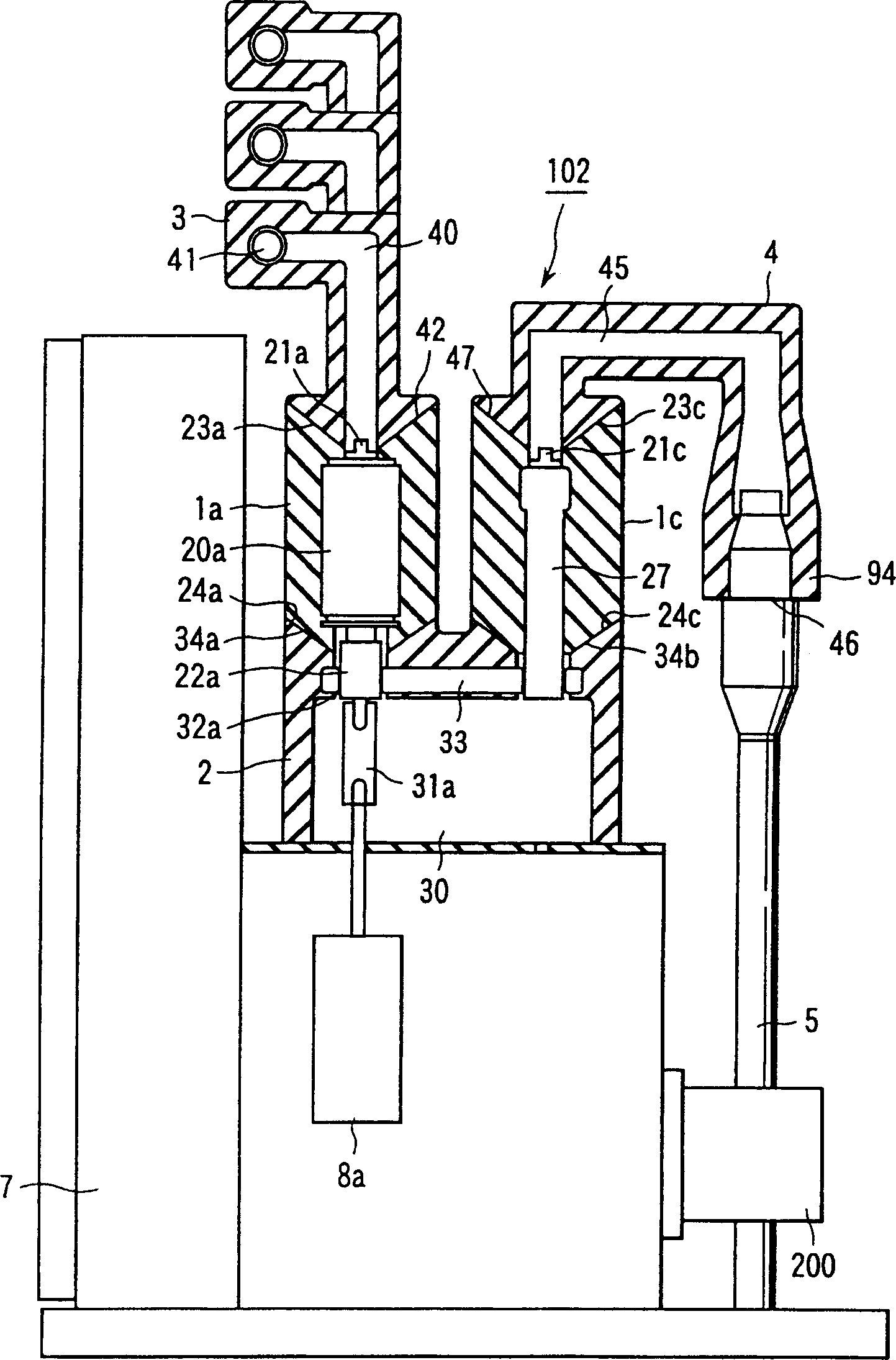
[0164] In the first embodiment described above, the plurality of connecting portions 34a and 34b provided in the valve moving side mold portion are arranged substantially in the same direction. In addition, a plurality of connection portions 34a and 34b are provided on a surface opposite to the hole surface of the insulating portion of the valve moving side mold portion.
[0165] Therefore, various valve mold sections can be installed in the valve moving side mold section in the same direction.
[0166] In addition, since the surface of the valve die portion is provided with a ground layer, the distance between the valve dies can be reduced.
[0167] To drive the vacuum valve, an insulating operating rod is connected between the operating mechanism and the vacuum valve. They are set in closed holes in the valve moving side mold part. Insulated operating rods can be driven parallel to each other in the same direction. Therefore, the size of the valve moving side mold portion...
no. 3 example
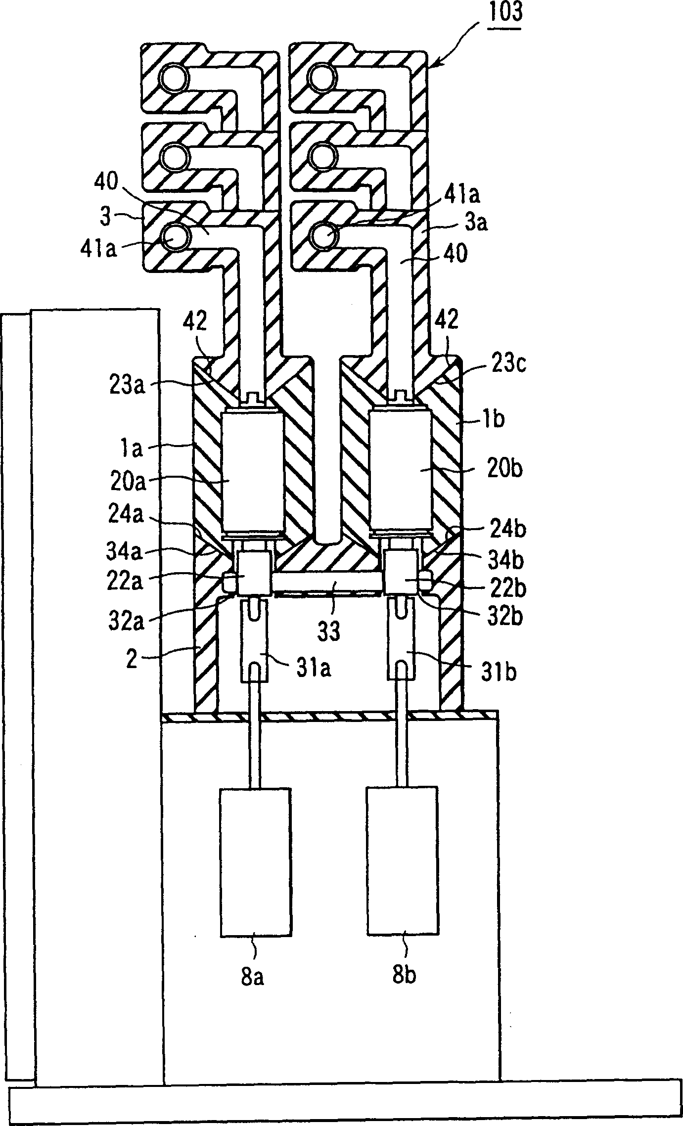
[0172] Figure 12 is a side sectional view showing an example of the structure of the enclosure switchgear according to the present invention. Figure 13 to Figure 15 is a schematic diagram showing an example of an electronic circuit composed of a switching device according to the present invention.
[0173] Figure 12 The switching device 110 is constituted by the Figure 13 Enclosed switchgear for electronic circuit c33 shown in .
[0174] In the switching device 110, the contact point 13 is provided in the conductor 33 connecting the connection parts 34a and 34b of the side mold part 2 with the valve movement. The contacts 13 are located on the valve moving side mold part 2 in which a closed hole 30 is formed.
[0175] The operating chamber 17 is provided with a grounding device operating mechanism 11 . One end of the movable conductor 12 is grounded. The movable conductor 12 is driven by the grounding device operation 11 . The other end of the movable conductor 12 i...
PUM
 Abstract
Description
Claims
Application Information