Straight bridge with changeable paths type crossroads
An overpass and lane-changing technology, which is applied to roads, roads, buildings, etc., can solve the problems of hidden dangers and safety hazards in the safe driving of vehicles
- Summary
- Abstract
- Description
- Claims
- Application Information
AI Technical Summary
Problems solved by technology
Method used
Image
Examples
Embodiment 1
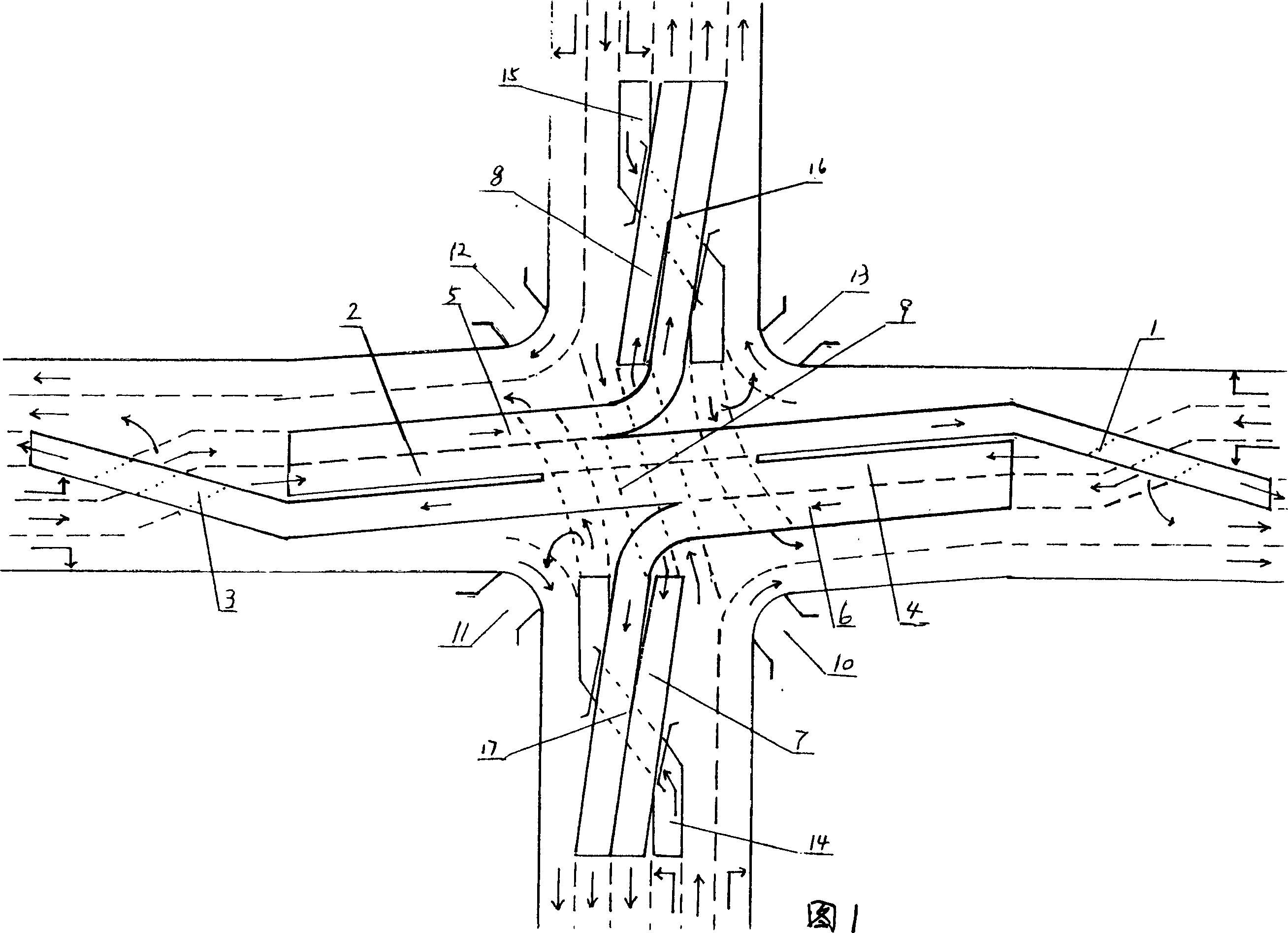
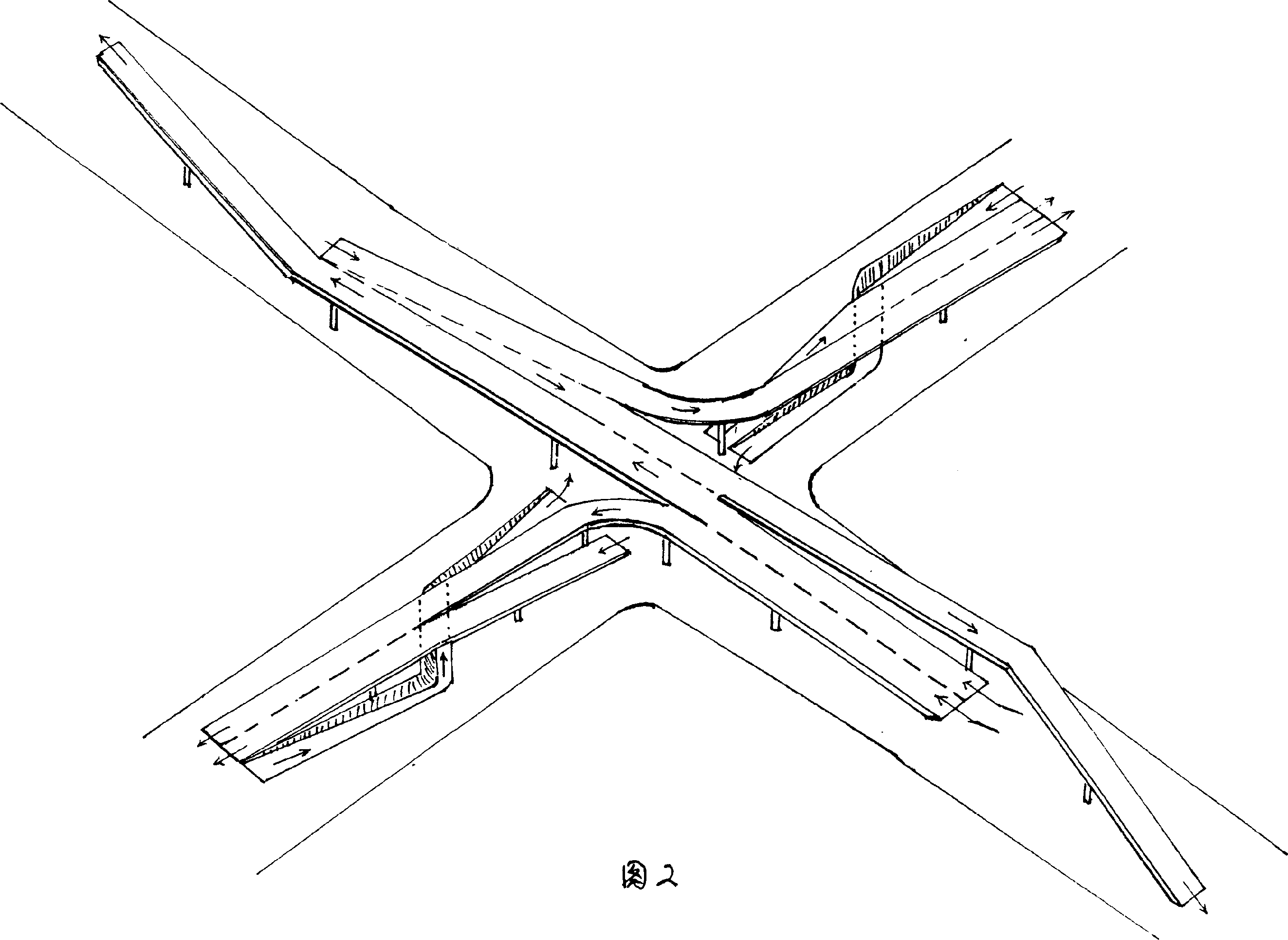
[0017] Referring to Fig. 1, 2, 5, two straight bridge lane-changing bridges 7 and 8 starting points are arranged on the longitudinal roads intersecting at the intersection, and the starting points are positioned at the respective forward road inboards at the crossing, and the center 16, 17 to the end point and the left-turn bridge 5 1 / 2 of the length of the downhill slope of 6 and 6 are connected as a whole, and the end points end at the inner sides of the respective reverse roads at the far intersection; The starting points of 14 and 15 are located on the inner sides of the respective forward roads at the far intersections. After crossing the two bridges and paralleling the center 16 and 17, the end point of the lane change ends at the middle road of the respective reverse roads at the near intersection; the graben intersects with 16 and 17 at the center It is the passing height of the road; but the height of the bridge and the depth of the graben are not limited to 1 / 2 of eac...
Embodiment 2
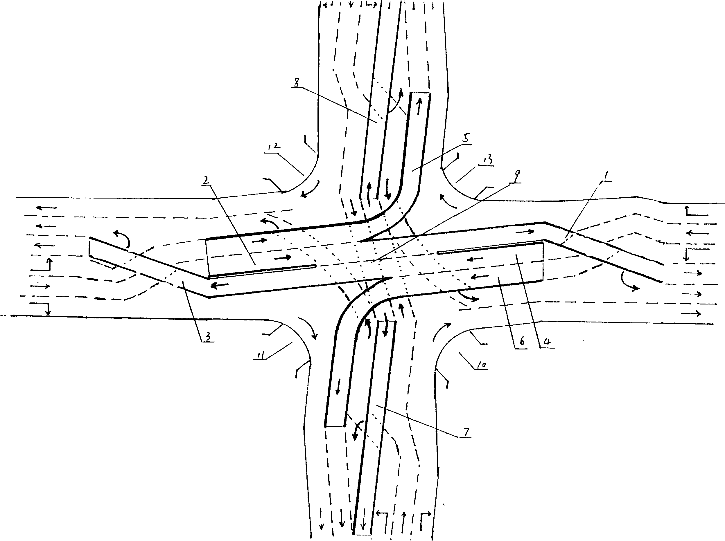
[0026] see image 3 , 4. Two straight bridge lane-changing bridges 7 and 8 are arranged on the longitudinal road intersected by cross roads. Swing bridge 5,6 conjoined, longitudinal road forward lane left-turn vehicle passes through straight bridge lane-changing bridge 7,8 center from ground road up and down and enters the inner side of respectively reverse lane and implements lane change. From image 3 As can be seen from the comparison of Fig. 2, the difference between the present embodiment and embodiment 1 is that the straight bridge lane change bridge 7,8 is a viaduct, it is not conjoined with the left turn bridge 5,6, and 1 / 2 passes through the height Road cutting 14,15 is therefore canceled, and all the other structures and vehicle flow direction all arrive with embodiment 1, so not tiresome state.
Embodiment 3
[0028] Referring to Fig. 6, the straight bridge lane change method of the straight bridge lane change overpass is also applicable to the underground single-layer traffic network system. In this embodiment, there is no structure above the ground level, and two straight roads are arranged on the longitudinal roads of the crossing roads. The underpass tunnels 7 and 8 that change lanes have their starting points located on the inner sides of the respective forward lanes at the near intersections, and the end points end at the inner sides of the respective reverse lanes at the far intersections, and the original bridges 1, 2, 3, 4, 5, and 6 on the transverse roads , 9 are replaced by the underpass type tunnel, and the underground single-layer full intercommunication overpass formed by bridges 20, 21, 22, 23, 24 on the ground at the vehicle interchange is connected to the two banks of the tunnel. The present embodiment layout structure is completely consistent with embodiment 2, and ...
PUM
 Abstract
Description
Claims
Application Information
 - R&D
- Intellectual Property
- Life Sciences
- Materials
- Tech Scout
- Unparalleled Data Quality
- Higher Quality Content
- 60% Fewer Hallucinations
Browse by: Latest US Patents, China's latest patents, Technical Efficacy Thesaurus, Application Domain, Technology Topic, Popular Technical Reports.
© 2025 PatSnap. All rights reserved.Legal|Privacy policy|Modern Slavery Act Transparency Statement|Sitemap|About US| Contact US: help@patsnap.com


