Sealed compressor partition plate structure

A compressor and plate structure technology, applied in the field of compressors, can solve problems such as impact noise, worn bearing surface, fluid leakage, etc., and achieve the effect of preventing impact noise and preventing wear

Inactive Publication Date: 2003-10-29
LG ELECTRONICS (TIANJIN) APPLIANCES CO LTD
View PDF0 Cites 0 Cited by
  • Summary
  • Abstract
  • Description
  • Claims
  • Application Information

AI Technical Summary

Problems solved by technology

[0011] However, in the above-mentioned conventional hermetic compressor, such as figure 2 and image 3 As shown, the parts θ1 and θ2 where the curved surface 5a and the surface 5b of the partition plate 5 combine form an angle, so when the baffles 6A and 6B move, a slight deviation occurs, and fluid leakage and impact noise will occur, and wear The contact surfaces of the baffles 6A, 6B or the bearing surfaces of the bearings 3A, 3B

Method used


Image

  • Sealed compressor partition plate structure
  • Sealed compressor partition plate structure
  • Sealed compressor partition plate structure

Examples


Embodiment Construction

[0021] Below in conjunction with accompanying drawing and specific embodiment the present invention is described in further detail:

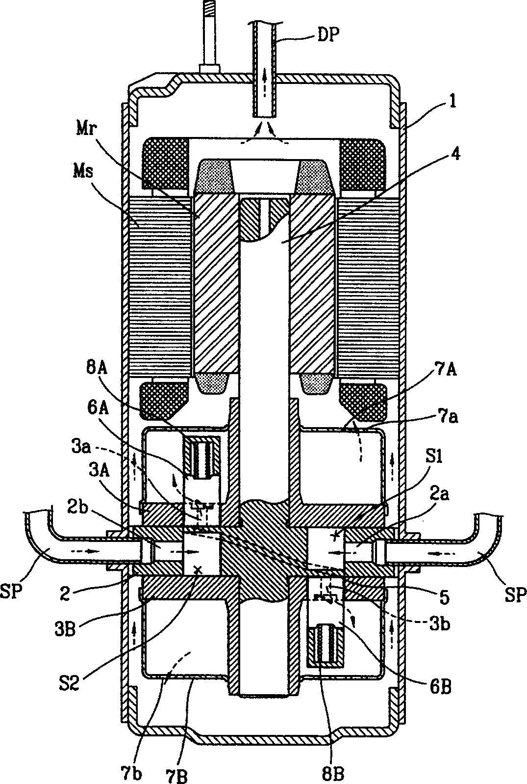
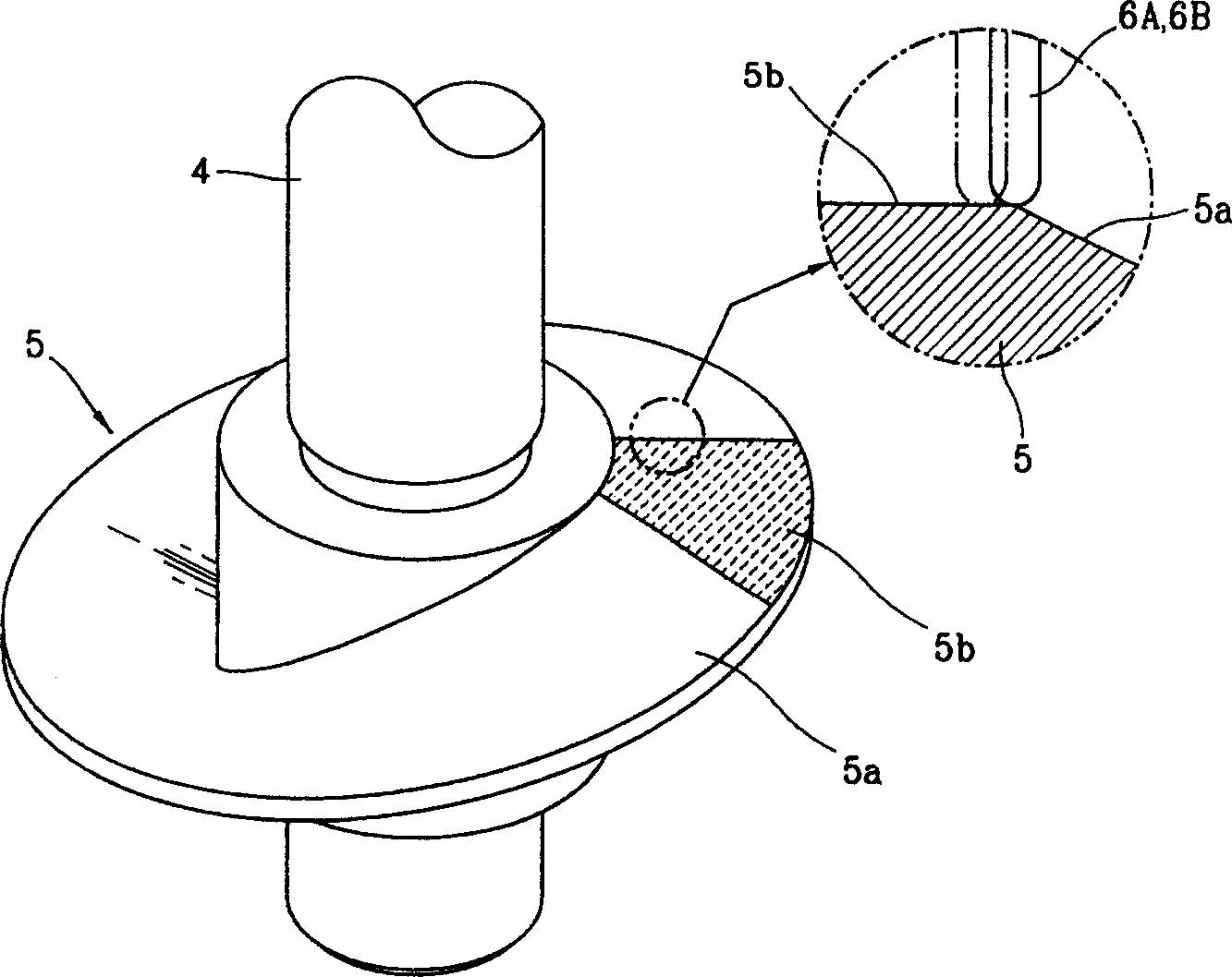
[0022] Such as figure 1 , 4 , 5, the present invention is provided with a hermetic compressor with a partition plate comprising the following structure: a motor part composed of a stator Ms and a rotor Mr fixed on the upper half of the housing 1; a motor part fixed on the lower half of the housing 1 Cylinder 2; the first bearing 3A and the second bearing 3B that are fixed on the top and bottom of the cylinder 2 together to form the inner space of the cylinder 2; combined with the rotor Mr of the motor part and simultaneously connected to the rotating shaft 4 of each bearing 3A, 3B; and The rotating shaft 4 combines or forms a division plate 10 that divides the interior of the cylinder 2 into the first space S1 and the second space S2; the lower end and the upper end respectively contact the upper and lower sides of the division plate 10, and wh...


PUM


Abstract

A dividing plate structure of enclosed compressor is disclosed. It is inserted in the internal space of cylinder to divide it into at least two sealed spaces. The barriers is in contact with the upper and lower surfaces of dividing plate for switching said sealed space between suction space and compression space. It feature is that the upper and lower surfaces of dividing plate are curved surfacefor decreasing impact noise and friction.

Description

technical field [0001] The invention relates to a compressor, especially an invention on the structure of a compressor partition plate. Background technique [0002] Generally speaking, in a hermetic compressor, the baffle moving in a straight line is tangent to the rotating shaft. The baffle divides the inner space of the cylinder into a suction area and a compression area. When the rotor rotates, the suction area is switched according to the phase difference of the rotor. and compression zone, and continuously inhale, compress and discharge fluid. [0003] figure 1 A longitudinal sectional view showing a conventional hermetic compressor. As shown in the figure, a conventional compressor is composed of a motor part provided in a casing 1, which is powered by a stator Ms and a rotor Mr, and a compressor part connected with the rotor Mr to suck, compress and discharge fluid. [0004] The structure of the compressor part is: the cylinder 2 fixed on the lower half of the hou...

Claims


Application Information

Patent Timeline
Patent Type & Authority Applications(China)
IPC IPC(8): F04C18/356
Inventor 史范东梁光植
Owner LG ELECTRONICS (TIANJIN) APPLIANCES CO LTD
Why Eureka
Try Eureka