Partition plate structure for closed compressor

A technology of dividing plates and compressors, applied in rotary piston machinery, rotary piston/swing piston pump parts, mechanical equipment, etc., can solve the problems of fluid leakage, impact noise, wear, etc.

Inactive Publication Date: 2006-03-29
LG ELECTRONICS (TIANJIN) APPLIANCES CO LTD
View PDF0 Cites 0 Cited by
  • Summary
  • Abstract
  • Description
  • Claims
  • Application Information

AI Technical Summary

Problems solved by technology

However, in conventional hermetic compressors, the parts θ1 and θ2 of the contact surfaces of the curved surface 5a and the surface 5b of the partition plate 5 form a raised shape, and a slight floating pheno...

Method used


Image

  • Partition plate structure for closed compressor
  • Partition plate structure for closed compressor
  • Partition plate structure for closed compressor

Examples


Embodiment Construction

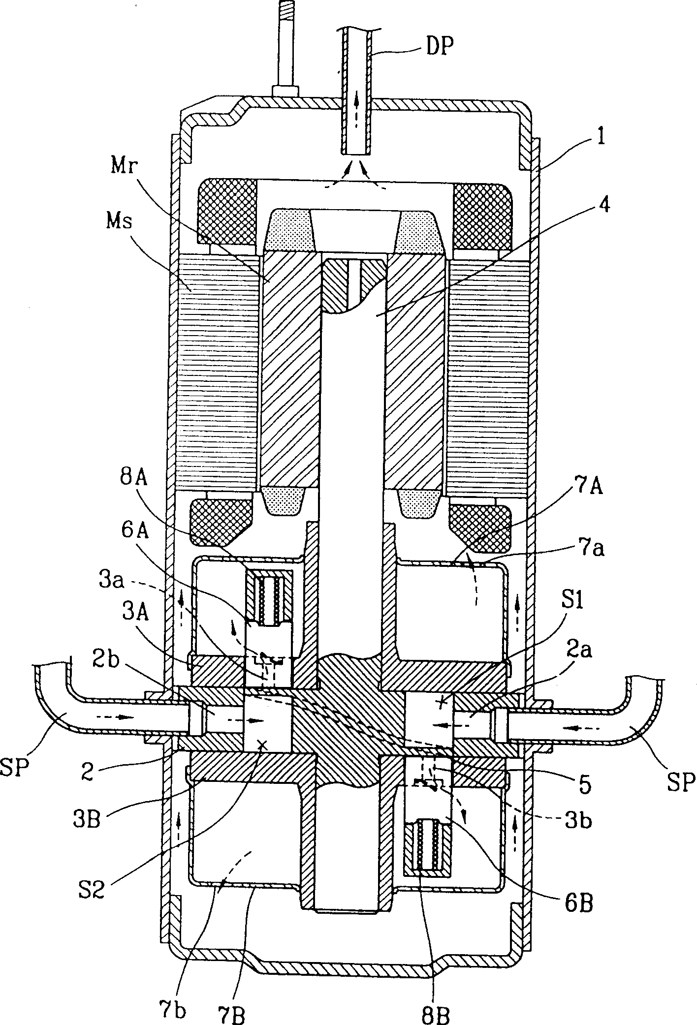
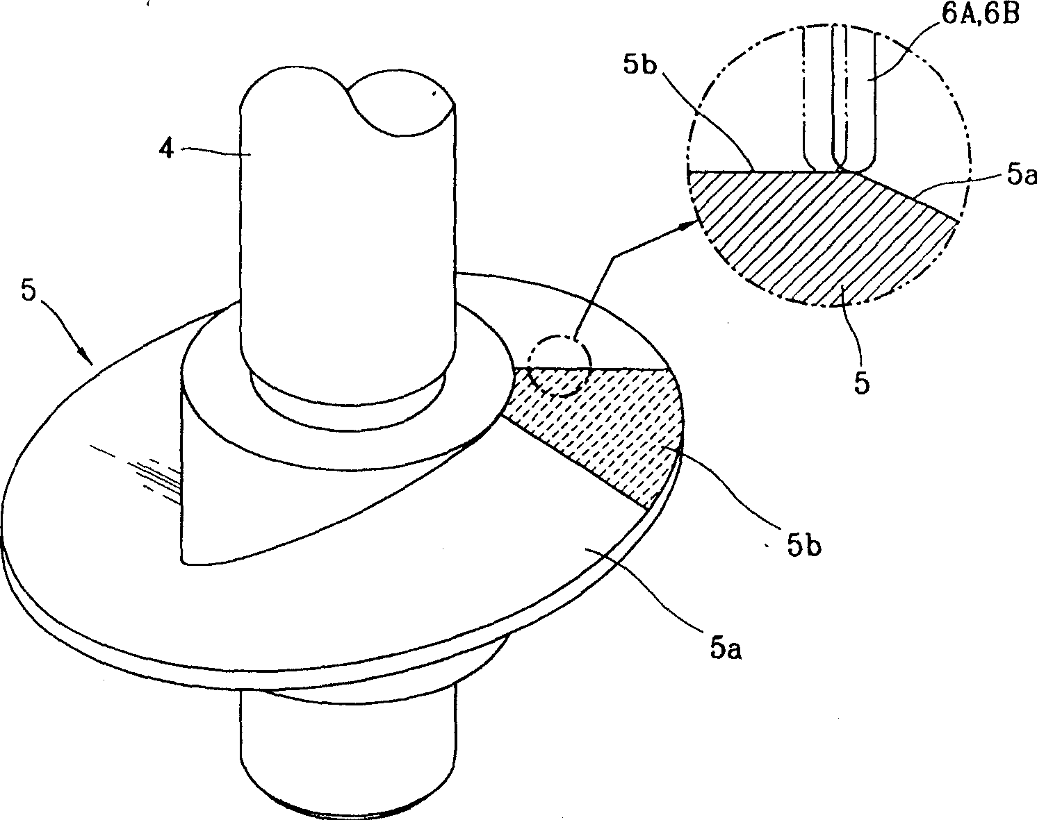
[0017] The structure of the partition plate of the hermetic compressor of the present invention is specifically described below in conjunction with the accompanying drawings and embodiments:

[0018] Such as figure 1 , 4 , 5, the partition plate structure of the hermetic compressor of the present invention includes the cylinder 2, the first support plate 3A, the second support plate 3B, the rotating shaft 4, the partition plate 10, the first sliding plate 6A and the second Slider 6B. Among them, the cylinder 2 is connected to one side of the motor assembly and fixed in the lower half of the casing 1; the first support plate 3A and the second support plate 3B are respectively fixed on the upper and lower sides of the cylinder 2 to form the inner space of the cylinder 2 together; The rotating shaft 4 is connected to the motor assembly, and at the same time passes through and combines with the support plates 3A, 3B to transmit the power of the motor assembly to the compressor a...


PUM


Abstract

In the invention, a division inserted in the internal space of the cylinder with a suction port and a discharge port can divide the internal space into at least two or more closed spaces, and on two sides of the division is pressed-in a jointed sliding-vane. While rotating, each closed space is changed into suction and discharge zones. Two sides of the division being in contact with the sliding vane form zones with different curvatures to make the angle between the axial vertical centre-line and the inclined plane pass the vertical centre-line continuous change in the range between 25 deg. to 70 deg. The vanes are always in the state in contact with cam surface to prevent producing impact noises between the vanes and the division.

Description

technical field [0001] The invention belongs to a device of a hermetic compressor, in particular to a partition plate structure of a hermetic compressor in which the planes at the top dead centers on both sides of the partition plate are connected to the other curved surfaces by curves. Background technique [0002] The sliding vane compressor is a sliding vane that moves linearly and contacts the rotating body, which divides the inner space of the cylinder into a suction area and a compression area. When the rotating body rotates, the suction area and the compression area are continuously converted to each other according to the phase difference of the rotating body. Simultaneous suction, compression, discharge fluid. Such as figure 1 , 2 , 3, the conventional compressor includes a motor assembly and a compressor assembly. The motor assembly includes a stator Ms and a rotor Mr to generate power at the inner upper portion of the housing 1 . The compressor assembly is con...

Claims


Application Information

Patent Timeline
IPC IPC(8): F04C29/00F04C18/00
Inventor 杨广植师范东
Owner LG ELECTRONICS (TIANJIN) APPLIANCES CO LTD
Why Eureka
Try Eureka