Signal light

A signal lamp and lampshade technology, applied in the field of signal lamps, can solve the problem of high cost

Inactive Publication Date: 2003-11-12
BARTEC COMPONENETE & SYST
View PDF0 Cites 1 Cited by
  • Summary
  • Abstract
  • Description
  • Claims
  • Application Information

AI Technical Summary

Problems solved by technology

In addition, the cost of this structure is also high

Method used


Image

  • Signal light
  • Signal light

Examples


Embodiment Construction

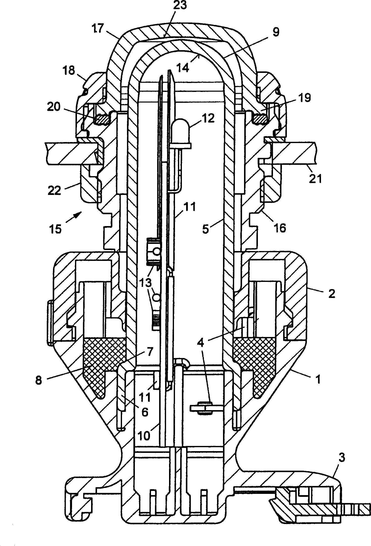
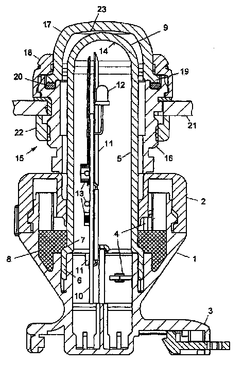
[0008] The signal lamp according to the invention has a housing 1 with a cover 2 and a base 3 which is fastened on a profiled rail not shown in the figures. Electrical conductors 4 for connecting electrical input and output lines or terminals, also not shown in the figure, are provided in housing 1 .

[0009] In addition, a lampshade 5 made of light-transmitting material is arranged in the housing 1, which is basically designed as a tube with a cylindrical cross section, which passes through the cover 2 and protrudes upwards. The part of the lampshade 5 located in the housing 1 has a rectangular tube end 6 anchored in the housing 1 , the rectangular dimensions of this part being slightly larger than the rest of the lampshade 5 . A shoulder 7 is formed at the beginning of the tube end 6 due to the larger rectangular dimensions. In this region, the lampshade 5 is cast in a ring by means of the casting resin 8 which is injected into the housing 1 and overlaps the shoulder 7 . T...


PUM


Abstract

The signaling light has a housing (1) with electrical conductor parts (4), a LED (12) arranged in a light rod (5) with a transparent light cap (9) whose internal surface (14) facing the LED has a fine bubble structure. At least the light cap of the light rod is colored with a milky color. At least the cap can be colored with a fluorescent milky color.

Description

technical field [0001] The invention relates to a signal lamp for use as an optical indication. Background technique [0002] Most of the known light indicators equipped with light-emitting diodes have insufficient light distribution and non-uniform light emission, so that the indication is poor compared with the light emitted by incandescent lamps. There are various types of light emitting diodes with different light emitting configurations. LEDs with narrow beam angles produce bright, precise point emission, but not area emission. Light-emitting diodes with wide light-emitting angles cannot produce sufficient brightness to meet the requirements as a noticeable signal. It is already known to use so-called multi-LED strips with a plurality of light-emitting diodes. However, this variant is relatively expensive and does not provide much improvement in luminous performance. Furthermore, it generates a large amount of heat, so that it cannot be used in explosion-hazardous a...

Claims


Application Information

Patent Timeline
Patent Type & Authority Applications(China)
IPC IPC(8): F21S8/00F21V5/02F21V25/02F21Y115/10G08B5/36
CPCY10S362/80F21V25/02F21W2111/00F21S8/00F21Y2101/02F21Y2115/10
Inventor 莱因霍尔德·巴利安卡尔-海因茨·勒克斯
Owner BARTEC COMPONENETE & SYST
Why Eureka
Try Eureka