Bullet lock having bullet groups with different elastic forces

A pin group and pin lock technology, which is applied in the field of pin locks, can solve problems such as non-prevention of technical opening, inability to control the sliding level of magnetic pins, and restrictions on the amount of pin sets, and achieve reliable anti-theft performance, low manufacturing cost, and a large number of keys. big effect

Inactive Publication Date: 2003-12-10
李东春
View PDF2 Cites 4 Cited by
  • Summary
  • Abstract
  • Description
  • Claims
  • Application Information

AI Technical Summary

Problems solved by technology

[0005] The invention solves the problem that the traditional mechanical pin locks locked by the upper and lower layers of pins cannot prevent technical opening; it solves the problem of the existing traditional mechanical pin locks locked by the upper and lower pins and the single-layer pins in the lock cylinder The anti-theft tumbler lock with side column locking structure has the problem that the sliding direction of a

Method used


Image

  • Bullet lock having bullet groups with different elastic forces
  • Bullet lock having bullet groups with different elastic forces
  • Bullet lock having bullet groups with different elastic forces

Examples


Embodiment Construction

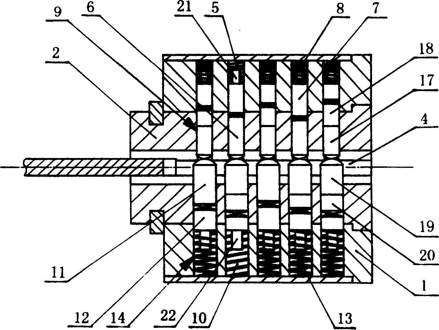
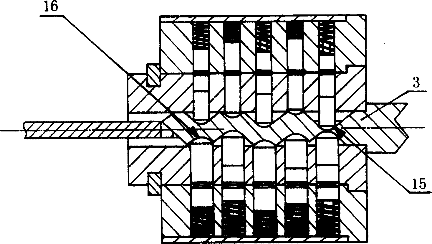
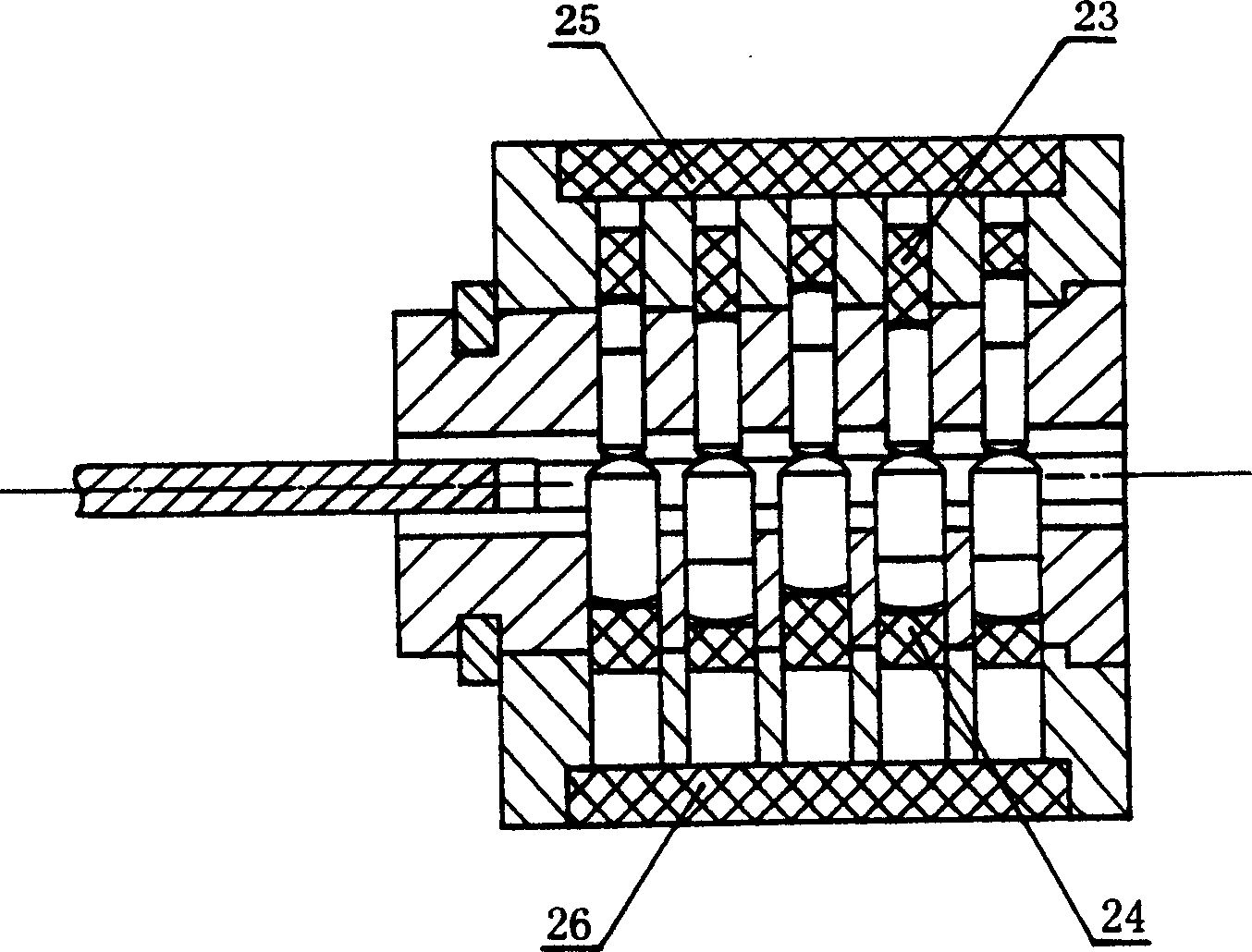
[0018] A tumbler lock with groups of tumblers of unequal elastic force, comprising a lock cylinder body 1 , a lock cylinder 2 and a key 3 . exist figure 1 , 2In the described embodiment, a row of relatively thin pinholes 5 is provided on one side of the lock core body 1 through the lock core body 1 and the lock core 2 to the keyhole 4, and a corresponding number of relatively thin pin holes 5 are inserted. A relatively thin pin group 9 composed of an upper pin 6, a relatively thin lower pin 7 and a relatively weak compression spring 8; on the other side corresponding to the lock core body 1, a penetrating lock core body 1 and a lock core 2 are provided. A row of relatively thick pinholes 10 to the keyhole 4 is inserted into a corresponding number of relatively thick pinholes composed of relatively thick upper pins 11, relatively thick lower pins 12 and relatively strong compression springs 13. Set of 14 marbles. When the key 3 is not inserted, a row of relatively thick pin ...


PUM


Abstract

The present invention relates to a billiard latch with two rows of billiard groups which are different each from other in spring force in which one row of billiard groups is thinner one and another row of billiard groups of thicker one which can prop said thiner row of billiard groups against its hole position, and said billiard latch is characterized by that when the billiard groups are arbitrarily slidden, said two rows of billiard groups are alternatively or simultaneously being in the state of preventing said billiard latch from being technically unlatched.

Description

technical field [0001] The invention relates to a pin lock, in particular to a pin locking structure of the pin lock. Background technique [0002] The existing upper and lower layers of mechanical pin locks locked by pins all have to slide in the opposite direction of the spring force in the unlocking direction of all the pin groups, so they cannot prevent technical opening. Specifically, a tool is used to twist the lock cylinder to force the pinholes to be misaligned and the lower pins are clamped at the dislocation of the pinholes, and then all the lower pins are pushed into the pinholes on the lock core one by one by turning the upper pins. However, the lower pin that is pushed into the pin hole on the lock core body will not enter the pin hole on the lock cylinder due to being blocked by the dislocation of the pin hole, and the upper pin is also blocked by the dislocation of the pin hole. Will not be pushed into the pin hole on the lock cylinder body. Therefore, the t...

Claims


Application Information

Patent Timeline
IPC IPC(8): E05B15/12E05B27/06E05B47/04
Inventor 李东春
Owner 李东春
Why Eureka
Try Eureka