Supercharge Your Innovation With Domain-Expert AI Agents!

Apecture grid type display device and method for controlling brightness

A display and aperture grid technology, applied in static indicators, cathode ray tube indicators, instruments, etc., can solve the problem that the electron beam cannot hit the fluorescent surface correctly

Inactive Publication Date: 2004-01-07
FUJITSU LTD
View PDF0 Cites 0 Cited by
  • Summary
  • Abstract
  • Description
  • Claims
  • Application Information

AI Technical Summary

Problems solved by technology

As a result, the electron beams do not strike the phosphor surface correctly, so that Figure 10B The vertical strip shown in the

Method used


Image

  • Apecture grid type display device and method for controlling brightness
  • Apecture grid type display device and method for controlling brightness
  • Apecture grid type display device and method for controlling brightness

Examples


Embodiment Construction

[0029] Hereinafter, the present invention will be explained in more detail with reference to examples and drawings.

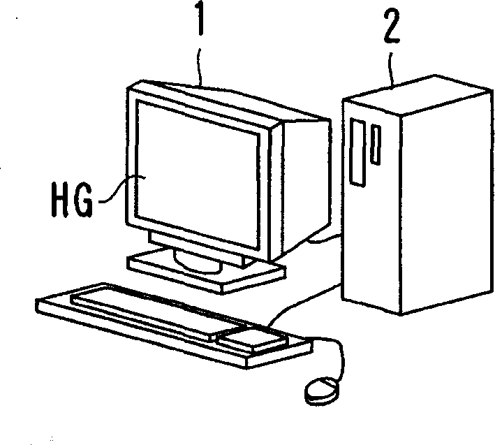
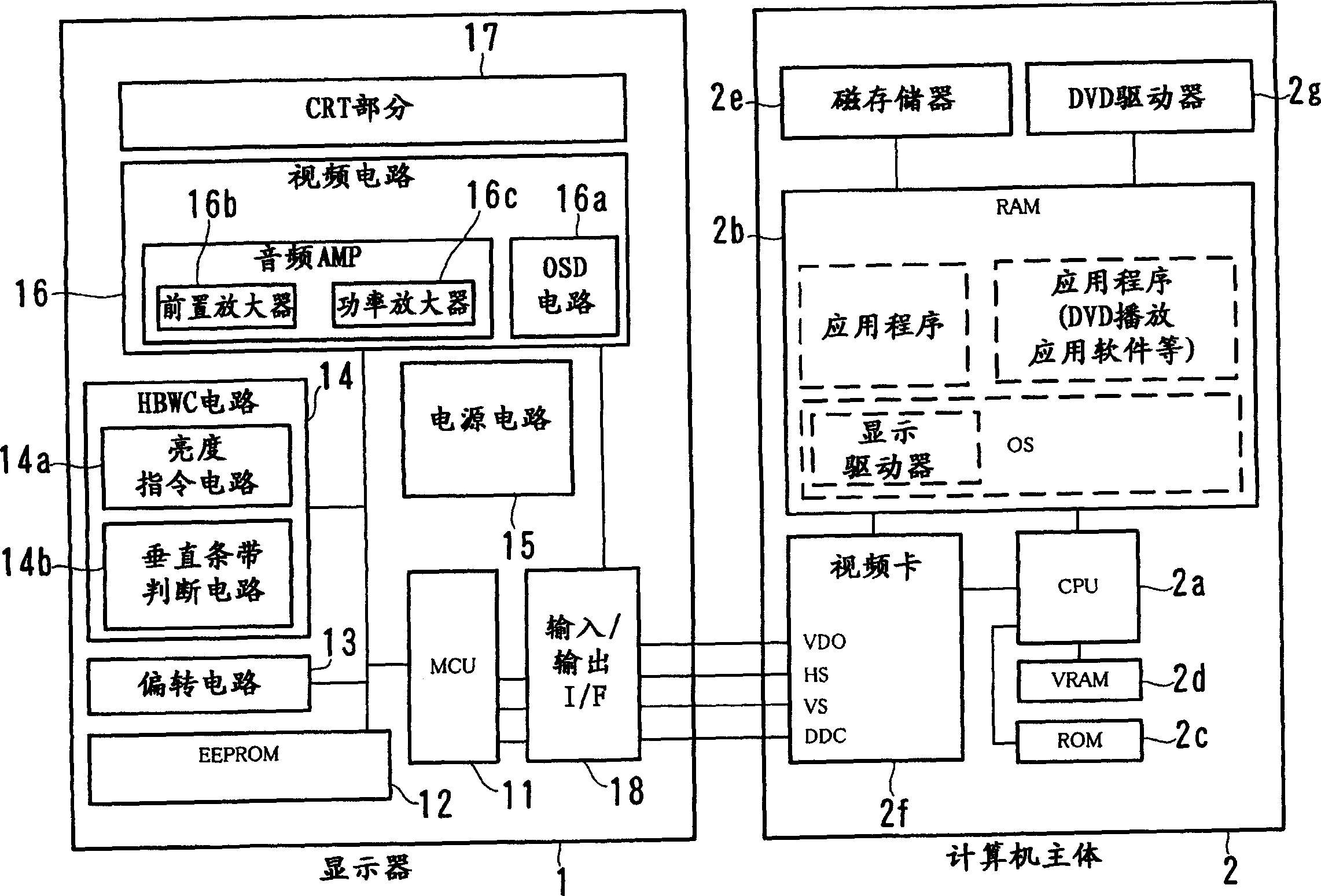
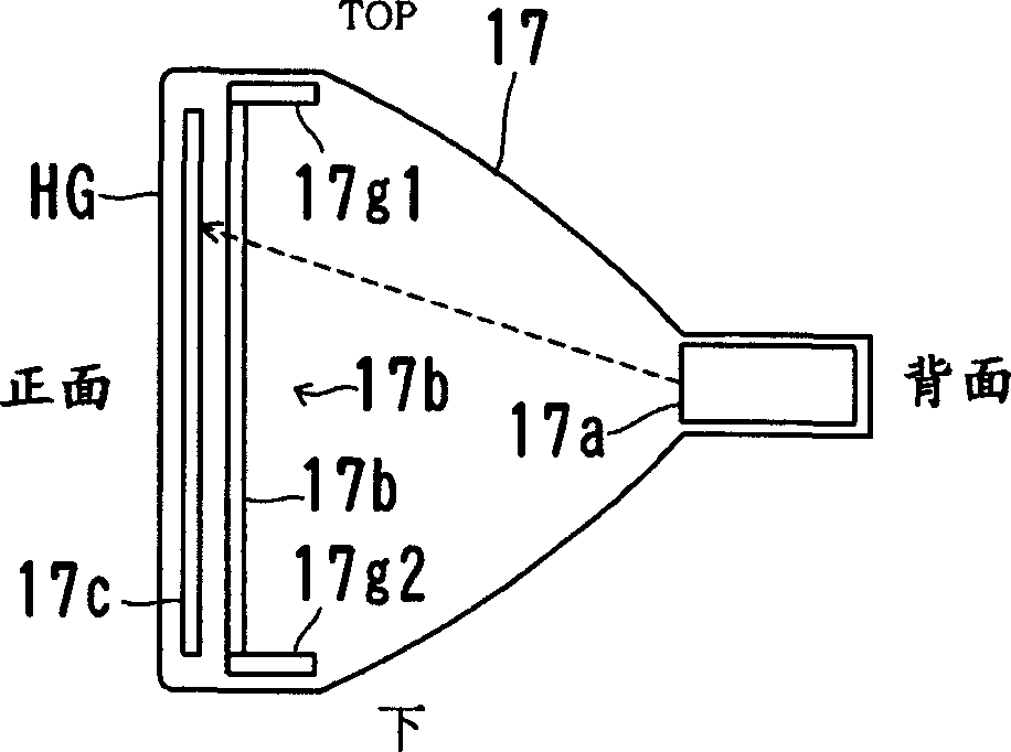
[0030] figure 1 An example of the appearance of the display 1 and the computer main body 2 according to the present invention is shown. figure 2 An example of the hardware configuration of the display 1 and the computer main body 2 is shown. Figure 3A and 3B The structure of the CRT portion 17 is shown. Figure 4 An example of the structure of the aperture grid 17b is shown. Figure 5A and 5B An example of the display images SN1 and SN2 displayed on the display screen HG is shown. Figure 6 Indicates the relationship between the length of the specified area in the x-direction and the y-direction and the appearance of the vertical strips. Figure 7A and 7B is a graph for comparing the presence or absence of vertical bands when the luminance values ​​L1 in specified areas are different from each other. Figure 8 is a flowchart illustrating the process ...


PUM


Abstract

An aperture grill type display device is provided that displays a picture including two areas whose luminance values are different from each other without vertical stripes. The aperture grill type display device includes an aperture grill to which plural wires are attached. When displaying a picture including a window whose luminance value is higher than that of a desktop, the luminance value of the window is decreased if the energy that electron beams emitted from an electron gun of the display device give to the wires for displaying the window exceeds the energy that the electron beams give to all the wires by a predetermined ratio.

Description

technical field [0001] The present invention relates to brightness control of an aperture grid display. Background technique [0002] Figure 9A -9C illustrates the color image display mechanism in a conventional CRT display 9. Figure 10A and 10B An example of the display image SN9 displayed on the display screen of the CRT display 9 is shown. The CRT part (Braun tube) of a conventional CRT display 9 includes an electron gun 91 , a color identification mechanism 92 and a fluorescent surface 93 . The fluorescent surface 93 includes stripe-shaped fluorescent films 93r, 93g, and 93b arranged in sequence and elongated in the vertical direction of the CRT display 9 . [0003] The electron gun 91 includes three cathodes 91r, 91g, and 91b that emit electron beams 8r, 8g, and 8b, respectively. There is an electron gun 91 having a cathode emitting three electron beams 8r, 8g and 8b. The emitted electron beams 8r, 8g, and 8b collide with fluorescent films 93r, 93g, and 93b, resp...

Claims


Application Information

Patent Timeline
Patent Type & Authority Applications(China)
IPC IPC(8): H04N5/68G09G1/00G09G1/28H04N5/57
CPCG09G1/28G09G2320/02G09G2320/0686H04N5/57
Inventor 金安修
Owner FUJITSU LTD
Features
  • R&D
  • Intellectual Property
  • Life Sciences
  • Materials
  • Tech Scout
  • Unparalleled Data Quality
  • Higher Quality Content
  • 60% Fewer Hallucinations
Learn More