Phase current detector

A detection device and current detector technology, which is applied in the direction of measuring devices, electromechanical transmission devices, and only current measurement, can solve the problems of narrowed operating range, difficulty in reducing ringing, and abnormal noise, so as to improve the accuracy of current detection and improve Current measurement accuracy and effect of reducing measurement errors

CN1478319AInactive Publication Date: 2004-02-25DAIKIN IND LTD
0 Cites 11 Cited by

Patent Information

Authority / Receiving Office
CN · China
Patent Type
Applications(China)
Current Assignee / Owner
Publication Date
2004-02-25
Estimated Expiration
Not applicable · inactive patent

Smart Images

  • Figure 1
    Figure 1
  • Figure 2
    Figure 2
  • Figure 3
    Figure 3
Patent Text Reader

Abstract

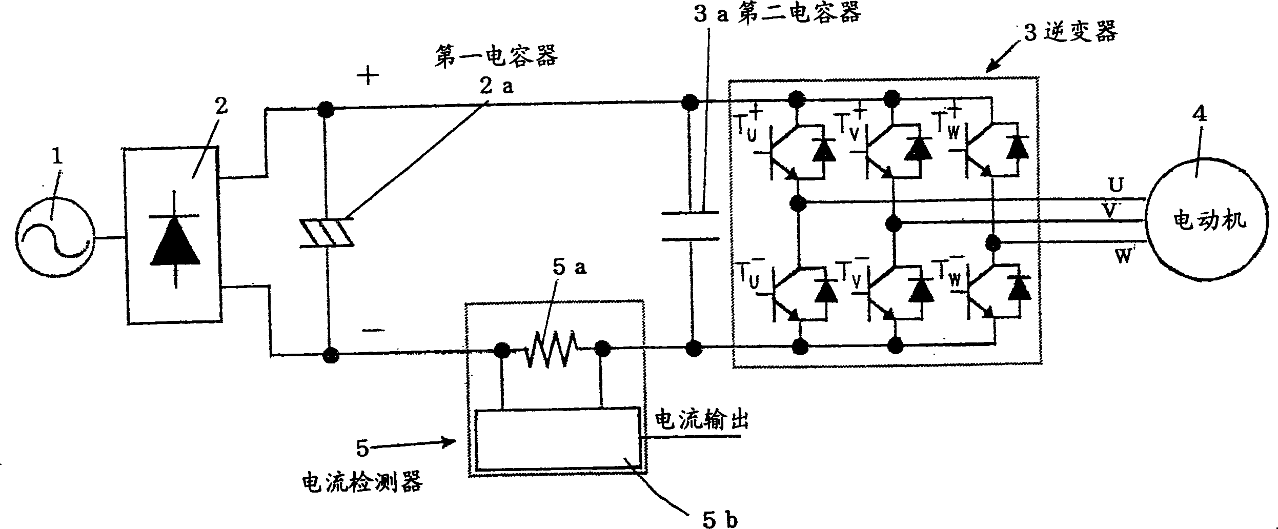
A first condenser (2a) is connected between output terminals of a rectifier circuit (2) which receives an AC power (1) as an input, and a three phase inverter (3) is connected in parallel with respect to the first condenser (2a), and output of the three phase inverter (3) is supplied to a motor (4), and a second condenser (3a) is connected in parallel to the input side of the three phase inverter (3), and a current detector (5) is connected between the first condenser (2a) and the second condenser (3a), and a third condenser is connected in parallel to the first condenser (2a) at a position slightly power side with respect to the current detector (5), and the capacitance of the second condenser (3a) is determined as small as possible within the range in which power devices are not destroyed by surge voltage due to switching, therefore, ringing is suppressed, and taking of current is performed rapidly and with high accuracy.
Need to check novelty before this filing date? Find Prior Art

Description

technical field

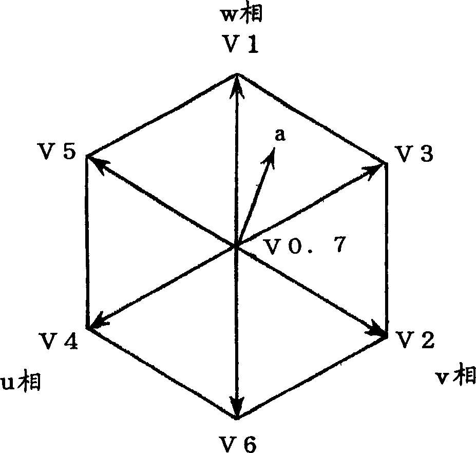
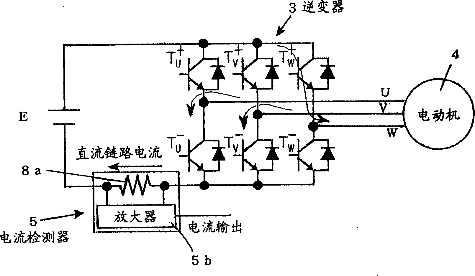
[0001] The present invention relates to a phase current detection device that detects a motor based on a current of a DC link and an additional vector diagram in a motor drive device that supplies an output from a PWM inverter to a motor and drives the motor phase current. Background technique

[0002] Conventionally, in a motor drive device in which an inverter drives a motor, a device for deforming an output pulse into a measurable output has been proposed as a device for detecting a motor phase current.

[0003] When the above-mentioned structure is adopted, the following disadvantages occur, namely, current measurement error due to ringing, waveform distortion due to extension of pulse output time, reduction of operating range, and generation of abnormal noise.

[0004] In particular, since no solution for ringing is proposed, there are disadvantages that it is difficult to reduce ringing, high-speed response cannot be performed, or measurement accuracy ...

Examples

Embodiment Construction

[0097] Embodiments of the phase current detection device of the present invention will be described in detail below with reference to the accompanying drawings.

[0098] figure 1 It is a figure which shows the structure of the motor drive apparatus using an inverter. Table 1 shows the relationship between the output voltage vector of the inverter (power device) and the switching state of the switching element.

[0099] T u + T v + T w +

V0

V1

V2

V3

V4

V5

V6

V7

OFF OFF OFF

OFF OFF ON

OFF ON OFF

OFF ON ON

ON OFF OFF

ON OFF ON

ON ON OFF

ON ON ON

[0100] Among them, T u + , T v + , T w + represent the switching elements of the upper bridge arms of the u-phase, v-phase, and w-phase respectively, T u - , T v - , T w - Indicates the switching elements of the lower bridge arm of the u-phase, v-phase, and w-phase respectively. In T...