
Antenna system of monitring electronic article, and its configuration

An electronic article monitoring and antenna system technology, applied in transmission systems, near-field transmission systems, electrical alarms, etc., can solve problems such as difficulty in adjusting the resonant frequency of antenna groups

Inactive Publication Date: 2004-03-10
上海维恩佳得数码科技有限公司
View PDF1 Cites 5 Cited by
  • Summary
  • Abstract
  • Description
  • Claims
  • Application Information

AI Technical Summary

Problems solved by technology

[0010] With a super rear system, it is difficult to tune the antenna group to the exact resonant frequency for different transmit modes

Method used


Image

  • Antenna system of monitring electronic article, and its configuration
  • Antenna system of monitring electronic article, and its configuration
  • Antenna system of monitring electronic article, and its configuration

Examples


Embodiment Construction

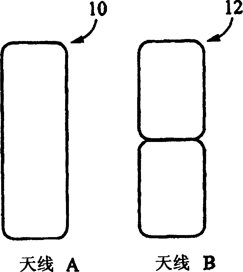
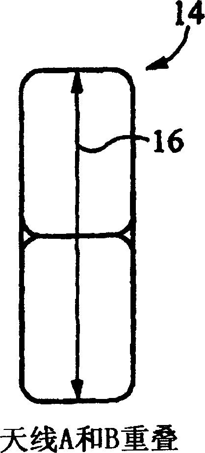
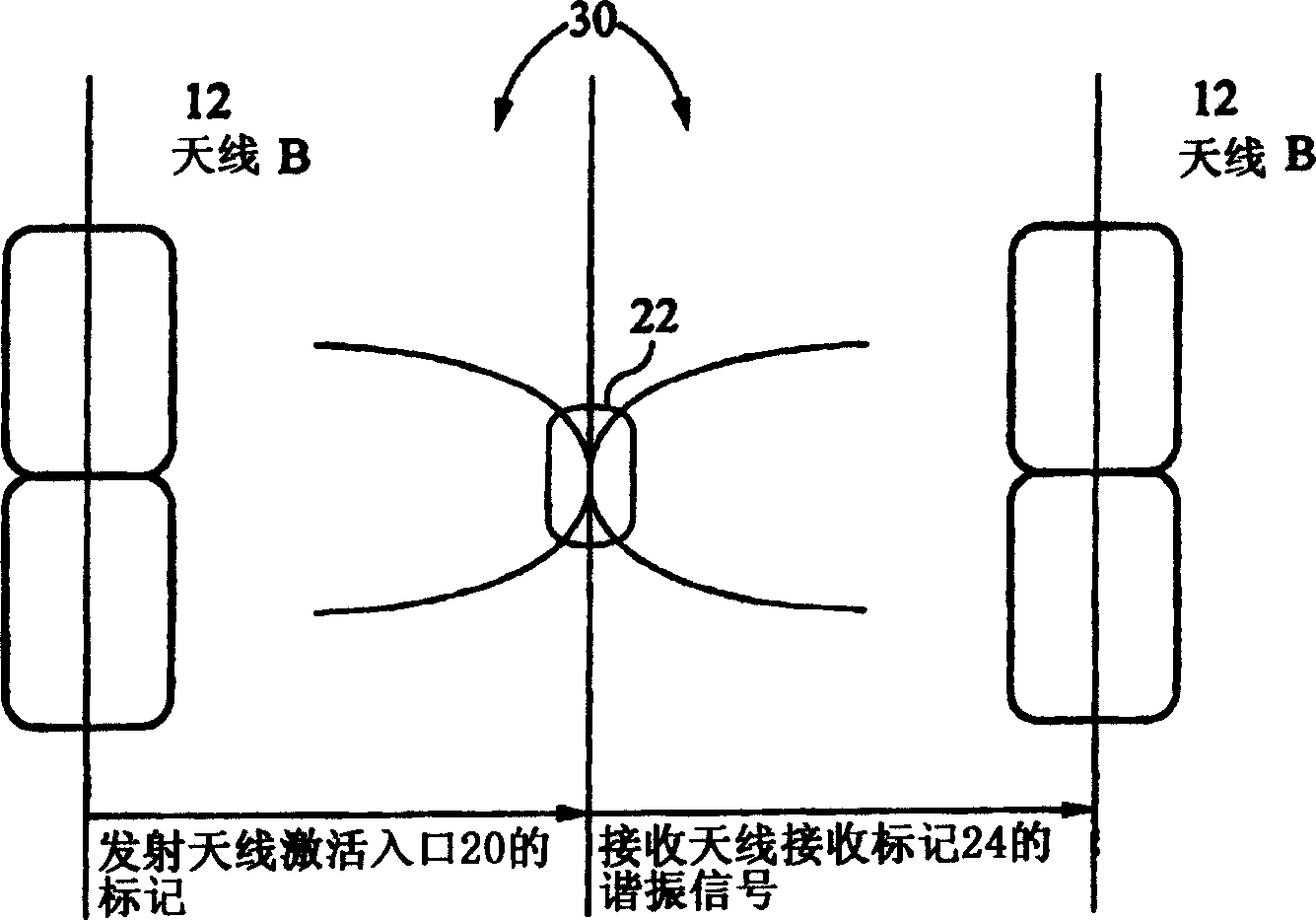
[0025] refer to figure 1 , according to a preferred embodiment of the present invention, two antennas of different shapes are used, each capable of transmitting signals into and receiving signals from the surveillance range. Antenna "A" 10 is a rectangular loop antenna and antenna "B" 12 is a figure-eight antenna.

[0026] figure 1 The antenna "A" 10 in the figure, that is, the rectangular loop is a continuous loop made of insulated wires overlapped to form a coil, which can be rectangular or elliptical. The rectangle or ellipse has an axis of elongation 16 . Rectangular ring structures are also called in-phase structures because the rings are driven by currents flowing in the same direction. figure 1 Antenna "B" 12 in , the "8" antenna, is accomplished by rolling insulated wire into a "8" shape to form two adjoining loops which may be rectangular or oval as shown. The "8" configuration is also known as an out-of-phase configuration because the rings are driven by currents...


PUM


Abstract

An antenna system for an electronic article surveillance system comprising: a first antenna and the second antenna mounted for use in an substantially overlapping manner, the first antenna configured as a loop, the second antenna configured in a "figure-8"; a control circuit for selectively activating one of the first and second antennas. The first and second antennas each operate as a transmit and receive antenna. The control circuit further comprises a switch to selectively enable operation of one of the antennas when the other is open circuit. One of the antennas transmits and receives while the other circuit, the vice versa. The loop antenna substantially detects markers oriented substantially perpendicular to an elongated axis when entering into a surveillance area. The "figure-8" antenna substantially detects markers oriented substantially parallel to an elongated axis when entering into a surveillance area.

Description

[0001] This application claims priority under 35 U.S.C. Section 119(e) to: Co-pending U.S. Provisional Patent Application Serial No. 60 / 374,920, filed April 22, 2002, entitled "Antenna System for Electronic Article Surveillance" Methods and Arrangements," and Serial No. 60 / 376,236, filed April 26, 2002, entitled "Methods and Arrangements for Antenna Systems for Electronic Article Surveillance." These two patents are also incorporated by reference into the application. technical field [0002] The present invention relates to the field of Electronic Article Surveillance (EAS) systems, and more particularly to ESA antenna systems for omnidirectional transmission and reception of signals. Background technique [0003] Antenna systems generally consist of two components located on either side of a store entrance or checkpoint corridor, usually referred to as gates, racks, panels or detectors. In many systems, one anten...

Claims


Application Information

Patent Timeline
IPC IPC(8): G08B13/22H01Q7/02H04B5/00
Inventor 杨晓晖
Owner 上海维恩佳得数码科技有限公司
Learn More