Novel mechanical lock

A mechanical lock, a new type of technology, applied in the field of locks, can solve the problems of easy mutual opening, easy demagnetization failure, low key quantity, etc.

Inactive Publication Date: 2004-03-31
曲泽
View PDF0 Cites 2 Cited by
  • Summary
  • Abstract
  • Description
  • Claims
  • Application Information

AI Technical Summary

Problems solved by technology

Its disadvantage is that the magnetic marbles and keys are very easy to demagnetize and fail when they are heated (greater than 180°C)
The magnetic m

Method used


Image

  • Novel mechanical lock
  • Novel mechanical lock
  • Novel mechanical lock

Examples


Embodiment Construction

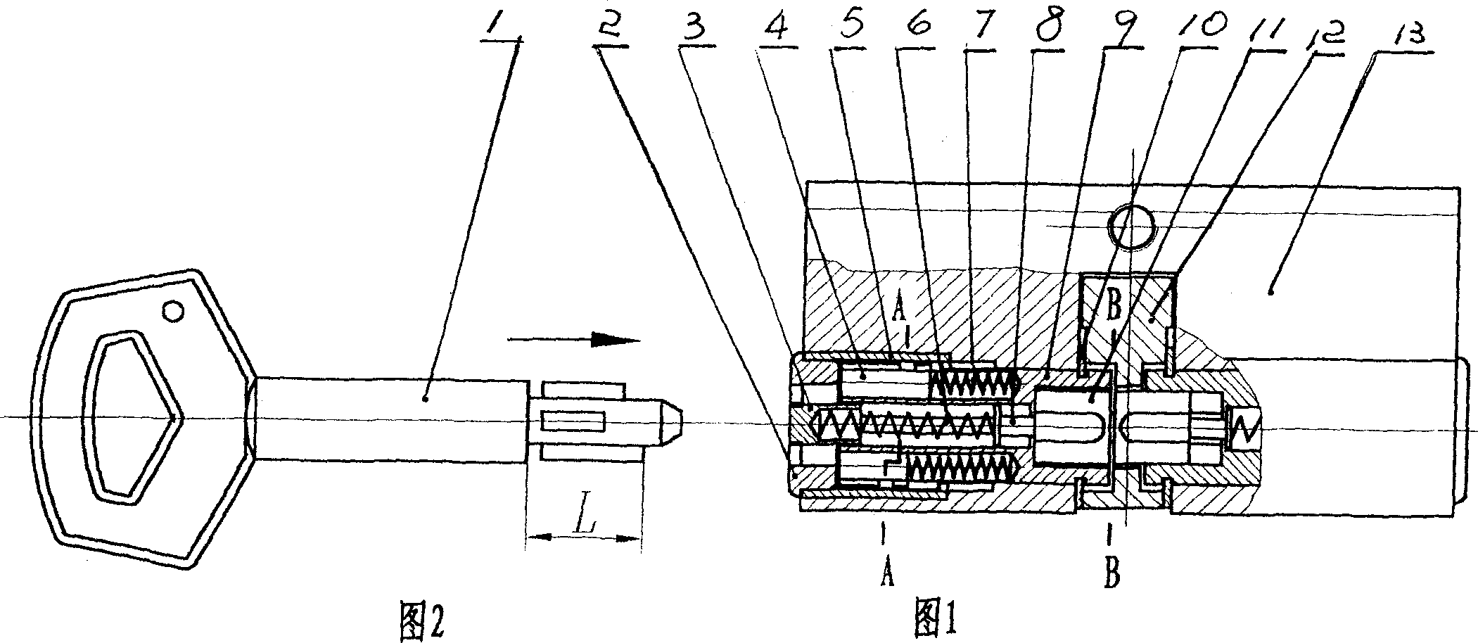
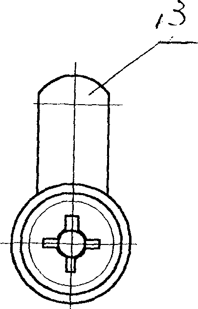
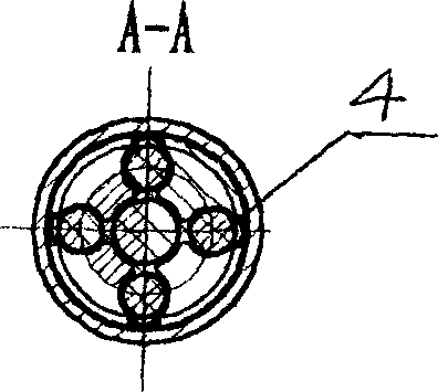
[0013] Working process: The end of the key (1) is processed with the same n rectangular teeth as the marble, with different thicknesses (one of the thick teeth is a positioning tooth), and the teeth with different lengths (Fig. 2) push the pin (4) shaft at the same time Move to the L length, the small plug (3) in the middle pushes the spring (7) and the push pin (8) to move the push block (11) into the groove of the toggle claw (12), at this time turn the key (1) to Complete the rotation of the lock cylinder. Toggle claw (12) rotates, stirs the cooperating parts of lockset, completes the unlatching work of lockset ( Figure 4 , 5 ). The key quantity index of lock cylinder (9) has close relation with ballistic groove number and the length variation of marble (4).

[0014] The formula for calculating the key amount ( l l 1 ) n

[0015] In the f...


PUM


Abstract

The invention discloses a novel mechanical lock wherein a housing and a lock tooth-like is arranged in the locking member, a ring form marble slide track and a center hole are arranged in the lock pin, a marble and a spring are arranged in the hole, the spring encloses the ejector pin on the left side, the motivation block is fixed in the lock pin, the right-hand side of the ejector pin is aligned with the groove of the motivation block, the motivation pawl is arranged on the lock pin, the lock pin is positioned by a retaining ring, the face cover is mounted above the lock member, the marble is pressed by the left side of the spring, the right-hand side of the spring contacts with the end surface of the lock pin

Description

technical field [0001] The invention relates to a novel mechanical lock, belonging to the field of locks. Background technique [0002] Common locksets on the market are basically divided into two classes: a class is a traditional tumbler lock, and the second class is a magnetic lock. Although there are different changes in appearance, the structure is to install a rotatable lock cylinder in the lock body. There are several holes drilled on the outer circle of the lock cylinder, and marbles and springs with different heights are installed in the holes. Under the action of the spring, the lock core cannot be rotated. The groove on the key is matched with the corresponding change of the height of the marble to achieve the rotation of the lock cylinder and complete the opening work of the lock. The tumbler lock with this structure, because the pins are not concealed, is easy to be unopened by means of hand detection, touch, toggle, etc., and because ...

Claims


Application Information

Patent Timeline
IPC IPC(8): E05B27/08
Inventor 曲泽郎永利
Owner 曲泽
Why Eureka
Try Eureka