Internal shield and cathode-ray tube containing it

A cathode ray tube, internal shielding technology, applied in the direction of cathode ray tube/electron beam tube, screen tube, discharge tube, etc., can solve screen inconsistency, CRT color purity, grating position, and convergence characteristics influence, insufficient screen boundary, etc. question

Inactive Publication Date: 2004-05-12
SAMSUNG SDI CO LTD
View PDF0 Cites 0 Cited by
  • Summary
  • Abstract
  • Description
  • Claims
  • Application Information

AI Technical Summary

Problems solved by technology

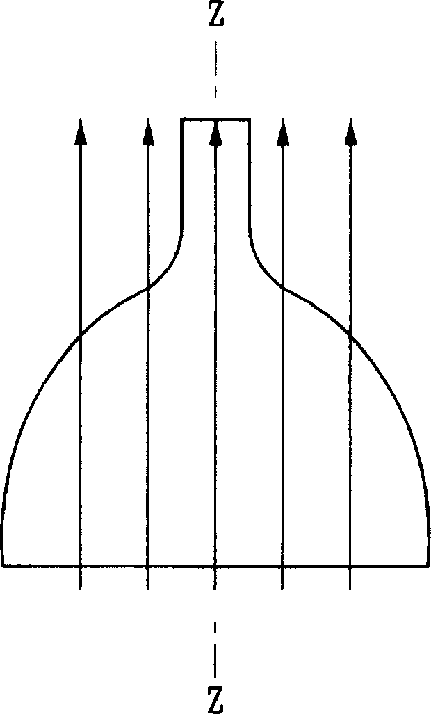
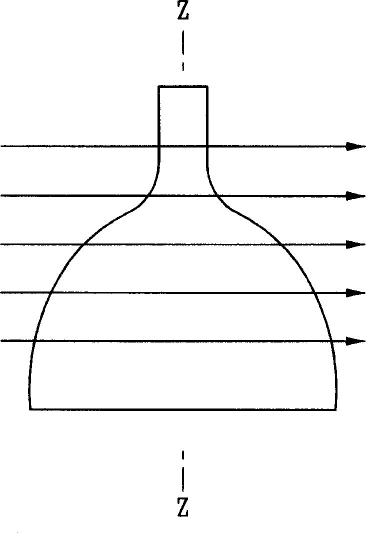
The paths of the three electron beams are altered by the Earth's magnetic field established by the Earth's north and south magnetic poles, thereby negatively affecting the color purity, raster position, and convergence characteristics of the CRT
However, in a CRT in which the shadow mask and the screen are formed into a planar structure, the amount of deviation on the screen is not uniform over the entire area of ​​the screen
That is to say, as far as the flat screen is concerned, the same electron beam emission angle deviation is converted into a larger deviation amount on the screen at the peripheral area of ​​the screen. For this reason, there is insufficient screen boundary in area ④ as described above.

Method used


Image

  • Internal shield and cathode-ray tube containing it
  • Internal shield and cathode-ray tube containing it
  • Internal shield and cathode-ray tube containing it

Examples


no. 1 example 1

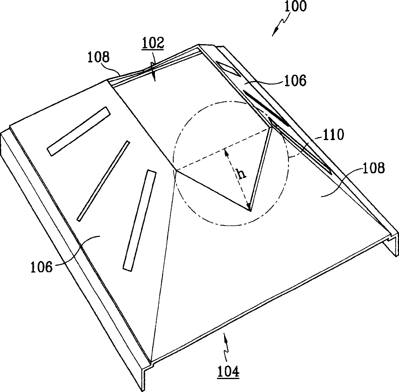
[0061] Like the first embodiment, the inner shield 28b of the second modified example includes a cutout portion 40b formed at the end of the short portion 32 where the electron gun opening 36 is formed. Each cutout portion 40b includes: two first cutout portions formed from the electron gun opening 36 and extending a predetermined distance toward the screen opening 38 at a predetermined angle; and a second cutout portion 44b formed from the first cutout portion 44b. The opening portion 42b is formed starting from where it terminates and extending toward the screen opening 38 in a predetermined arc for a predetermined distance.

[0062] If each second cutout portion 44b utilizes imaginary line extension to complete the circle starting from its circular arc, as Figure 7B As shown, then, the radius r3 of the circle is about 85mm. This radius increase compared to that of the first embodiment results in the first cut-out portion 42b being formed with a length ratio Figure 5 and...


PUM


Abstract

An inner shield for a cathode ray tube includes a screen opening and an electron gun opening through which electron beams pass, and a main body including a pair of long sections and a pair of short sections interconnected to form the screen opening and the electron gun opening. A cathode ray tube includes the inner shield. Each of the short sections includes a cutaway section having a pair of first cutaway sections formed starting from the electron gun opening and extending at a predetermined angle for a predetermined distance toward the screen opening, and a second cutaway section formed starting from where the first cutaway sections end and extending inwardly toward the screen opening, the second cutaway section being formed to extend past imaginary lines formed from where the first cutaway sections end to a furthermost inward point of the second cutaway section, that is, the point of the second cutaway section closest to the screen opening.

Description

technical field [0001] The present invention relates to an inner shield for a color cathode ray tube, and more particularly to an inner shield for a color cathode ray tube which can effectively block an external magnetic field such as the earth's magnetic field, so that electron beam errors caused by fluctuations in the external magnetic field can be avoided. The screen is reduced to a minimum. The invention also relates to a cathode ray tube comprising such an internal shield. Background technique [0002] A color cathode ray tube (CRT) is a display device in which a fluorescent screen is scanned by three electron beams emitted by an electron gun to achieve a specific image. The paths of the three electron beams are altered by the earth's magnetic field established by the earth's north and south magnetic poles, thereby negatively affecting the color purity, raster position, and convergence characteristics of the CRT. [0003] The Earth's magnetic field includes a vertical...

Claims


Application Information

Patent Timeline
Patent Type & Authority Applications(China)
IPC IPC(8): H01J29/02H01J29/06
CPCH01J2229/003H01J29/06H01J29/02
Inventor 金钟宪
Owner SAMSUNG SDI CO LTD
Why Eureka
Try Eureka