Door lock gear

A door lock and latch technology, applied in the field of door lock devices, can solve problems such as intrusion and immersion

Inactive Publication Date: 2004-08-11
AISIN SEIKI KK
View PDF1 Cites 20 Cited by
  • Summary
  • Abstract
  • Description
  • Claims
  • Application Information

AI Technical Summary

Problems solved by technology

Therefore, if there is a gap in the combined part between the case and the cover, water may intrude from the combined part and enter the drive mechanism.

Method used


Image

  • Door lock gear
  • Door lock gear
  • Door lock gear

Examples


no. 1 Embodiment approach

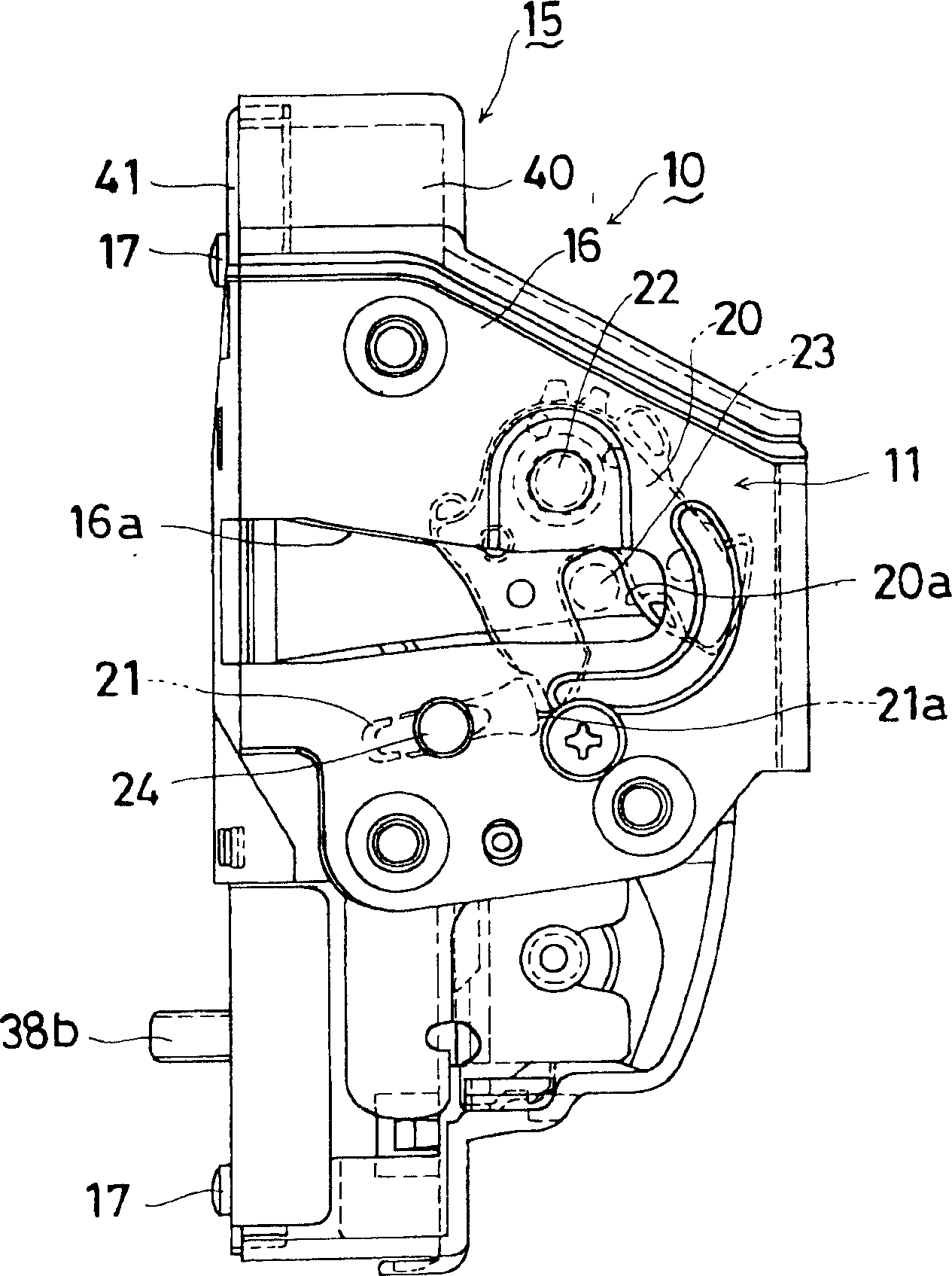
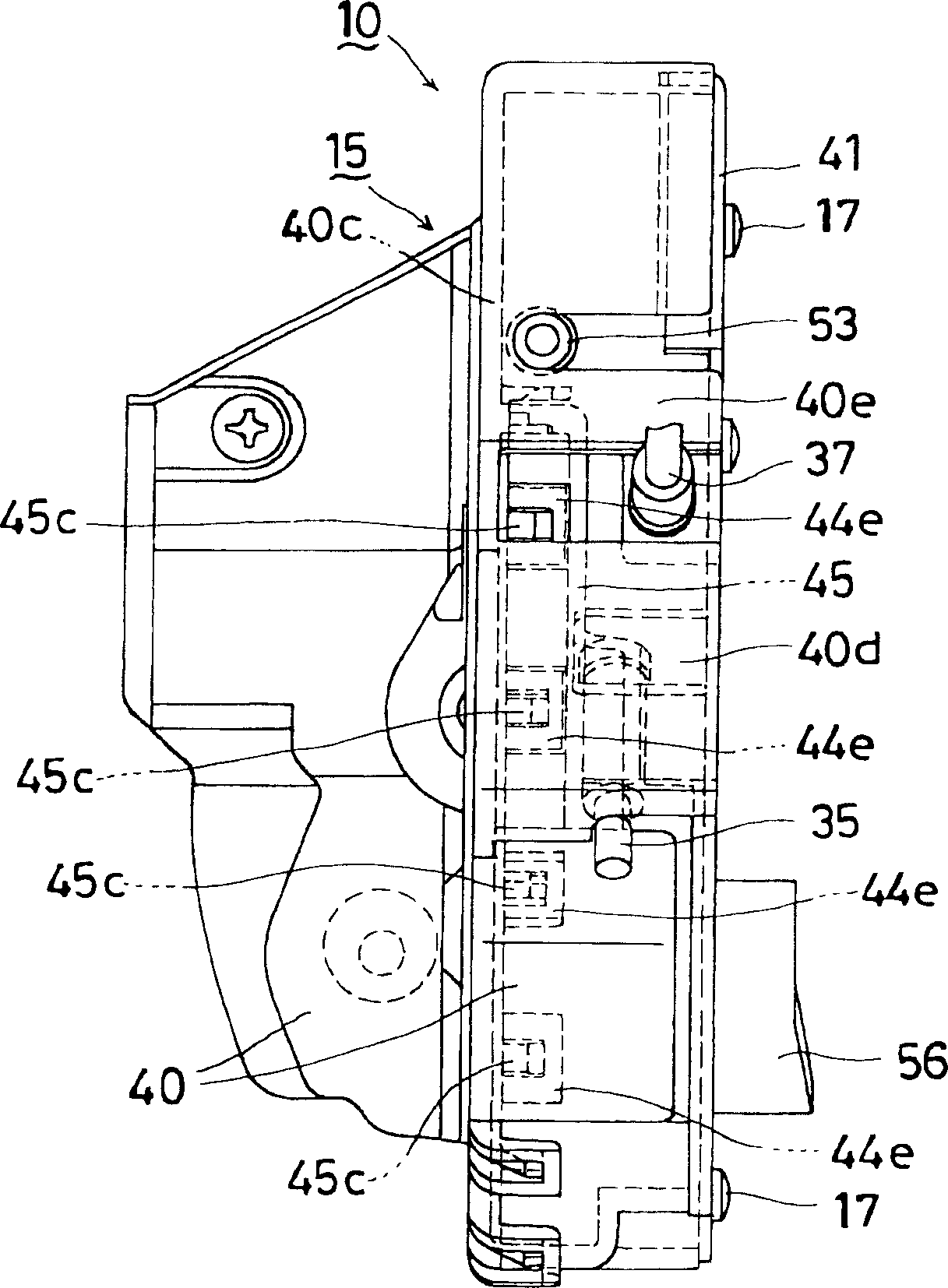
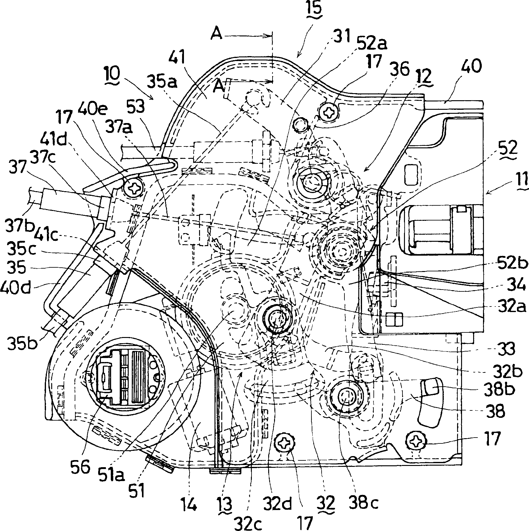
[0043] The door lock device 10 (door lock device) of the present invention is roughly composed of figure 1 The illustrated latch mechanism 11 (latch mechanism), opening unit 12 (opening unit) ( image 3 etc.), locking unit 13 (locking unit) ( image 3 etc.), motor 14 (actuator) ( image 3 etc.) constituted. These are integrally accommodated in the casing 15 (casing). This door lock device 10, its latch mechanism 11, in and figure 1The plane (hereinafter referred to as the 1st plane) that the shown paper surface develops in parallel constitutes, and the locking mechanism and the motor 14 that are made up of the opening unit 12 and the locking unit 13, are in the plane (the 2nd plane) (the 2nd plane) that develops perpendicularly with the 1st plane ( and figure 1 It is constructed in a plane developed in a direction perpendicular to the paper surface shown). Housing 15, included in the figure 2 Cover the locking mechanism and the part of the motor 14 in the shown right d...

no. 2 Embodiment approach

[0092] based on the following Figure 17 as well as Figure 18 The second embodiment will be described. In the second embodiment, compared with the first embodiment, the shape of the first inner opening lever 32a of the inner opening lever 32 is different. That is, the distance between the connection hole 32e and the canceling flange 32m of the first inside open lever 32a is shorter than that of the first embodiment.

[0093] (Opening operation inside the locked state)

[0094] In this embodiment, when the Figure 11 When the inner handle is operated in the corresponding locked state, it will act as follows. When the inside opening lever 32 rotates counterclockwise in the figure as a whole, first, the undo flange 32m of the first inside opening lever 32a presses the joining portion 52m of the resin rod 52a of the active lever 52 toward the lower left in the figure. The state after its action is as Figure 17 shown.

[0095] Along with the further movement of the inside ...

no. 3 Embodiment approach

[0100] based on the following Figure 19 The third embodiment will be described. The third embodiment differs from the first embodiment in the configurations of the casing 15 and the case 42 .

[0101] The case 15 is composed of a resin half case 61 and a resin cover 62 . On the half case 61, a flange portion 61b is formed along the peripheral end surface 61a thereof. On the other hand, in the cover 62, a groove portion 62b is formed along the peripheral end surface 62a. When the cover 62 and the half case 61 are combined, the flange portion 61b fits into the groove portion 62b, and a drain passage 63 communicating with the outside of the case 15 is formed between the fitted two peripheral end surfaces 61a, 62a.

[0102] The case body 42 is composed of a resin half case 64 and a resin cover 65 . The half-box 64 shares a reference wall 61c with the half-shell 61, and has a wall 64a protruding from the reference wall 61c. On the wall 64a of the case half 64, a groove portio...


PUM


Abstract

A door look device includes a latch mechanism engageable with or disengageable from a striker, an open unit transmitting an opening operation force to the latch mechanism for disengaging the latch mechanism from the engagement with the striker, a look unit transmitting locking and unlocking operation forces to the open unit for operating the open unit between an unlocking condition where the opening operation force is transmittable to the latch mechanism and a looking condition where the opening operation force is not transmittable to the latch mechanism, an actuator for outputting the looking and unlocking operation forces. The door look device further includes a housing for storing the latch mechanism, the open unit, the look unit and the actuator as a unit, and a case provided within the housing for accommodating at least the actuator.

Description

technical field [0001] The invention relates to a door lock device. Background technique [0002] As a conventional door lock device of this type, a device described in Patent Document 1 described later is known. [0003] The feature of this door lock device is that a door lock body provided with a two-position movable lever is equipped with an output member that can be moved at two positions by a drive mechanism such as a motor installed in the housing. In the door lock device in which the actuator and the joystick can be operated at two positions, the housing of the actuator fixed to the door lock body is integrally formed with the door lock that will include the joystick. The cover part that covers the joystick mounting surface of the main body. [0004] In the conventional door lock device described above, the driving mechanism is housed in the housing and closed by the cover. The combination between the housing and the cover is achieved only by the contact between th...

Claims


Application Information

Patent Timeline
Patent Type & Authority Applications(China)
IPC IPC(8): E05B83/36B60J5/00E05B77/34E05B85/02
CPCE05B85/02E05B81/06E05B81/72E05B81/16E05B77/34E05B77/265Y10T292/1047E05B85/00
Inventor 福永胜稔铃村淳大矢茂博村松明国松幸信西尾贵士田边茂
Owner AISIN SEIKI KK
Why Eureka
Try Eureka