Method and equipment for successive co-orientation solidification casting and manufactured wire rod or plate and belt material

A technology of directional solidification and wire, which is applied in the field of devices, wire or strip materials, and continuous directional solidification casting methods, can solve the problems of unable to manufacture ordinary wires for large current transmission, difficult to grasp the operation process, and difficult to control the operation process. Achieve the effects of wide application, excellent mechanical properties and convenient control

Inactive Publication Date: 2004-10-27
周照耀
View PDF3 Cites 7 Cited by
  • Summary
  • Abstract
  • Description
  • Claims
  • Application Information

AI Technical Summary

Problems solved by technology

The traditional directional solidification technology has the disadvantages of slow cooling rate and small temperature gradient, and can only produce small castings and short profiles with small cross-sections
The Chinese invention patent with the application number 01132329.9 describes a method for continuous liquid change directional solidification and continuous casting of primary aluminum. The continuous liquid change device and the directional solidification continuous casting device are used to melt the primary aluminum in the smelting and holding furnace. The mold is heated until the temperature exceeds the melting point of aluminum, the seed rod is placed in the mold, the aluminum liquid is introduced into the launder, and the liquid is changed at the solid-liquid interface of the casting rod with an electromagnetic pump and agitator, and the continuous casting speed is gradually increased. Accelerate to the stable stage and start to purify. This method has complicated equipment, and the speed of pulling the casting can only be determined by experience. The operation process is difficult to grasp, and only bars can be produced. The length of the prepared material is limited by the equipment structure and space.
The Chinese invention patent with application number 95103050.7 describes a continuous directional solidification casting process and equipment for special-shaped cylindrical thin-walled parts. The inner surface of the casting adopts the process method of directional solidification precision casting; the disadvantage of the above method is that the equipment structure is complicated, the relative movement rate of the mold or casting during the casting process can only be determined by experience, and the operation process is difficult to control. The shape and size of the manufactured parts are limited by the structure of the equipment, and only cylindrical parts or simple shape castings can be produced
The Chinese invention patent with the application number 02116581.5 discloses a process for preparing oxygen-free copper ultra-fine wire, using oxygen-free copper as raw material, adopting continuous directional solidification method to prepare oxygen-free copper rod with continuous columnar crystal structure with a diameter of 5-30mm The diameter of the copper rod is reduced to 8-15mm by cold rolling or warm rolling; then the drawing method is used for rough drawing and fine drawing. Due to phenomena such as end breakage and wire breakage, ultra-fine wires with a diameter of 10-50 μm are produced. Ultra-fine wires have high electrical conductivity, but due to the limited length of rod blanks obtained by directional solidification, it is impossible to manufacture ordinary wires for large currents. transmission

Method used


Image

  • Method and equipment for successive co-orientation solidification casting and manufactured wire rod or plate and belt material
  • Method and equipment for successive co-orientation solidification casting and manufactured wire rod or plate and belt material
  • Method and equipment for successive co-orientation solidification casting and manufactured wire rod or plate and belt material

Examples


Embodiment 1

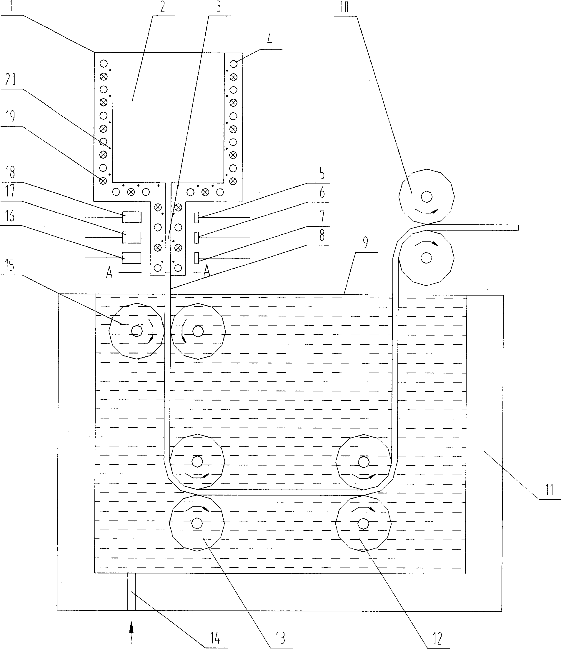
[0032] The specific structure of the continuous directional solidification casting device of the present invention is as figure 1 shown by figure 1 It can be seen that the continuous directional solidification casting device includes a crystallizer 1, a feed plate 8, a water tank 11, four sets of traction rollers 10, 12, 13, 15, X-ray generators 16, 17, 18 and X-ray sensors 5, 6 , 7, the water tank 11 is filled with water 9, the crystallizer 1 is located at the top of the water tank 11, and its bottom end has a crystallization port 3, and the wall of the crystallizer 1 is provided with a hollow cooling channel 4 and a heating wire 19 at the same time. The cooling passage 4 is connected to the cooling liquid supply member through the control valve, the heating wire 19 is connected to the power supply through the switch, and the control valve and the switch are connected to the control member; one end of the guide plate 8 can be extended into the crystallization port 3 to make t...

Embodiment 2

[0035] This embodiment is basically the same as Embodiment 1 except the following features: figure 1 The cavity 2 of the middle crystallizer is provided with a sealing cover to seal the cavity 2, and then the cavity 2 is evacuated to make the aluminum-magnesium alloy liquid release its dissolved gas, and then compressed gas is injected into the cavity 2 to A compressive stress of 1.5 MPa is applied to the liquid surface of the aluminum alloy in the cavity 2 by the gas.

Embodiment 3

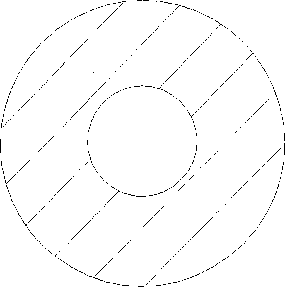
[0037] What this embodiment will prepare is the continuous directional solidification wire rod, and the continuous directional solidification casting device that it adopts is identical with the device that embodiment 1 adopts except following feature: the cross-sectional shape of crystallization port 3 is as follows image 3 As shown, it is a circular hole structure with a diameter of 3 mm, and a lead wire 8 is correspondingly arranged in the crystallization port 3; the four sets of traction rollers 10, 12, 13, 15 adopt a traction structure corresponding to the guide lead wire.

[0038] The specific operation steps of this embodiment are as follows: first, connect the lead wire 8 in the circular crystallization port 3 to form a bottom-closed cavity 2 in the crystallizer 1, and inject water 9 into the water tank 11 through the water inlet 14 on the water tank 11, After the water tank 11 is full, the water overflows from the edge of the upper mouth of the tank 11; the heating wir...


PUM

PropertyMeasurementUnit
diameteraaaaaaaaaa

Abstract

A casting method by continuous directional solidifying includes extending one end of drawing line or plate in crystallizing mouth, extending its another end is cooling liquid, preheating the crystallizer, pouring fluid material in the crystallizer, insulating for directional solidifying, and drawing said drawing line or plate to draw the solidified material in cooling liquid. Its apparatus is composed of crystallizer, drawing line or plate, cooling unit, drawing unit and check unit. Its product (wire or plate) features high quality and uniformity, and excellent performance.

Description

technical field [0001] The invention relates to the technical field of casting, in particular to a continuous directional solidification casting method, device and wire rod or strip material prepared therefrom. Background technique [0002] Since the directional solidification method was first used to study planar and cellular solidification in 1952, directional solidification technology has developed rapidly. This technique was originally used to eliminate the transverse grain boundaries generated during the crystallization process, thereby improving the unidirectional mechanical properties of the material. Because directional solidification technology can obtain some materials with special structure orientation and excellent performance, the main application of directional solidification technology is to produce castings with uniform columnar crystal or single crystal structure. Especially for the production of high-temperature alloy engine bla...

Claims


Application Information

Patent Timeline
Patent Type & Authority Applications(China)
IPC IPC(8): B22D11/041
Inventor 周照耀
Owner 周照耀
Why Eureka
Try Eureka