Steering post support device

一种支承装置、转向柱的技术,应用在转向柱领域,能够解决少冲击能量、形式不稳定、不稳定等问题

Inactive Publication Date: 2004-12-01
MITSUBISHI MOTORS CORP
View PDF2 Cites 21 Cited by
  • Summary
  • Abstract
  • Description
  • Claims
  • Application Information

AI Technical Summary

Problems solved by technology

[0005] The support structure disclosed in Japanese Patent Laid-Open No. Hei 11-115770 has the problem that the steering column cannot absorb energy when the steering column is released forward from the vehicle body in the vehicle length direction
[0006] Also, the support structure disclosed in Japanese Utility Model Publication No. 62-23771 has the problem that the position of the steering wheel held by the support pin for tilting the steering column (ie, the position of the steering wheel at the rear end of the steering column position) is unstable because the bearing pin moves; at the same time, the edge of the slot is crushed and therefore only little impact energy can be absorbed
Therefore, for example, when the airbag is mounted on the steering wheel, the form in which the airbag inflates toward the driver may be unstable

Method used


Image

  • Steering post support device
  • Steering post support device
  • Steering post support device

Examples


Embodiment Construction

[0014] The present invention will be described in detail below with reference to the accompanying drawings, which show preferred embodiments of the invention.

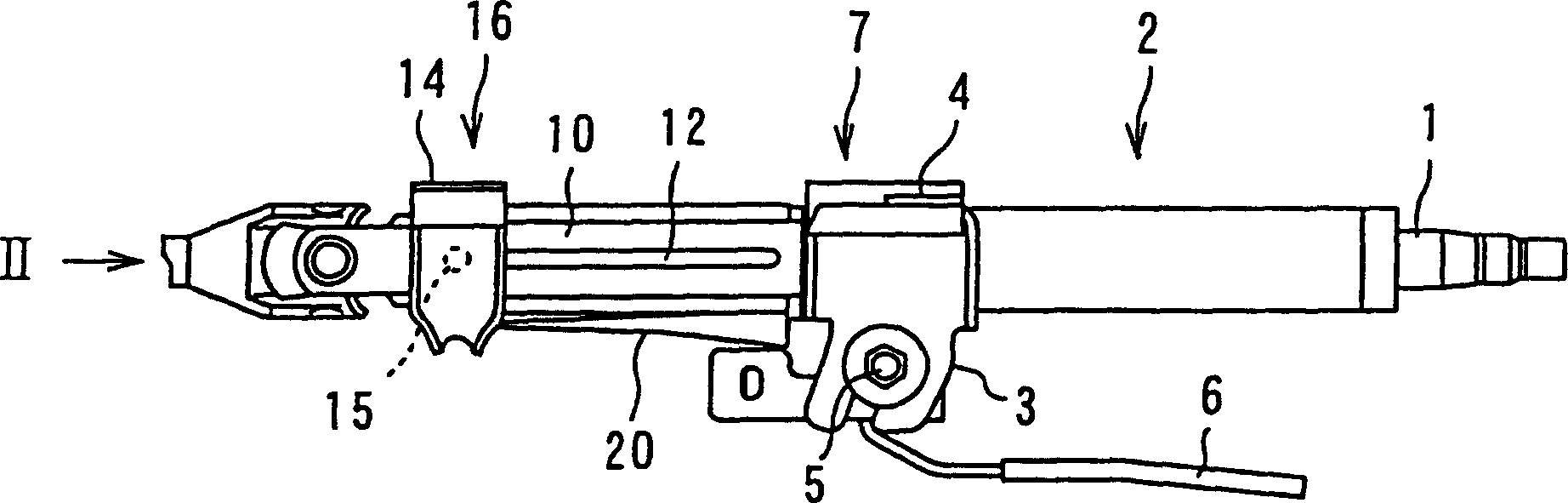
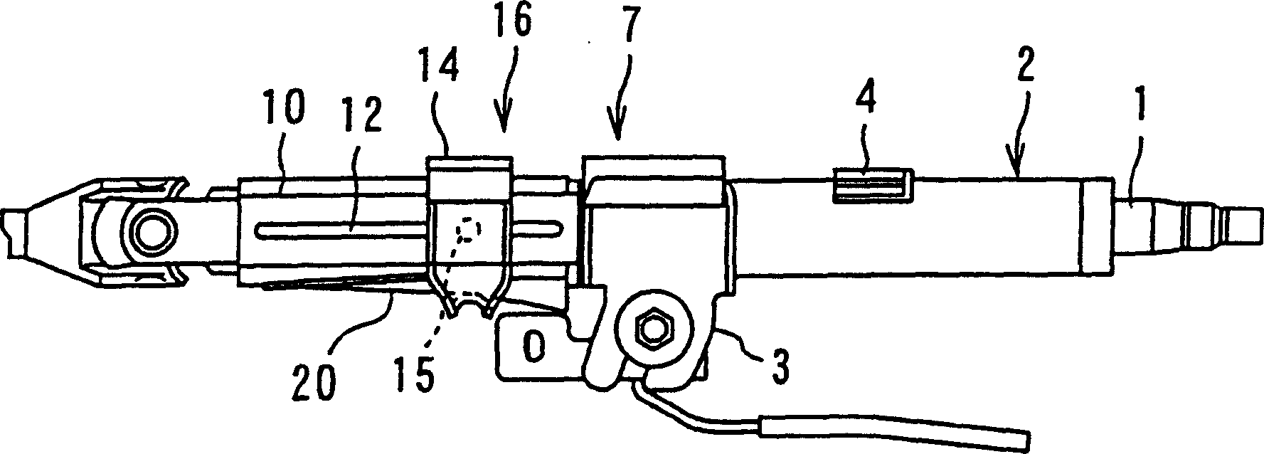
[0015] like Figure 1A As shown, the steering column 2 in which the steering shaft 1 of the vehicle is arranged is fixed approximately centrally on the vehicle body by a tilting rear mechanism 7 . The inclined rear mechanism 7 is known, and it includes: a cylindrical bracket 3, which is fixed on the steering column 2; a bellows 4, which is engaged with the cylindrical bracket 3 and fixed on the On the vehicle body; a tilt fixing shaft 5 engaged with the column bracket 3; and a tilt operating lever 6 and the like.

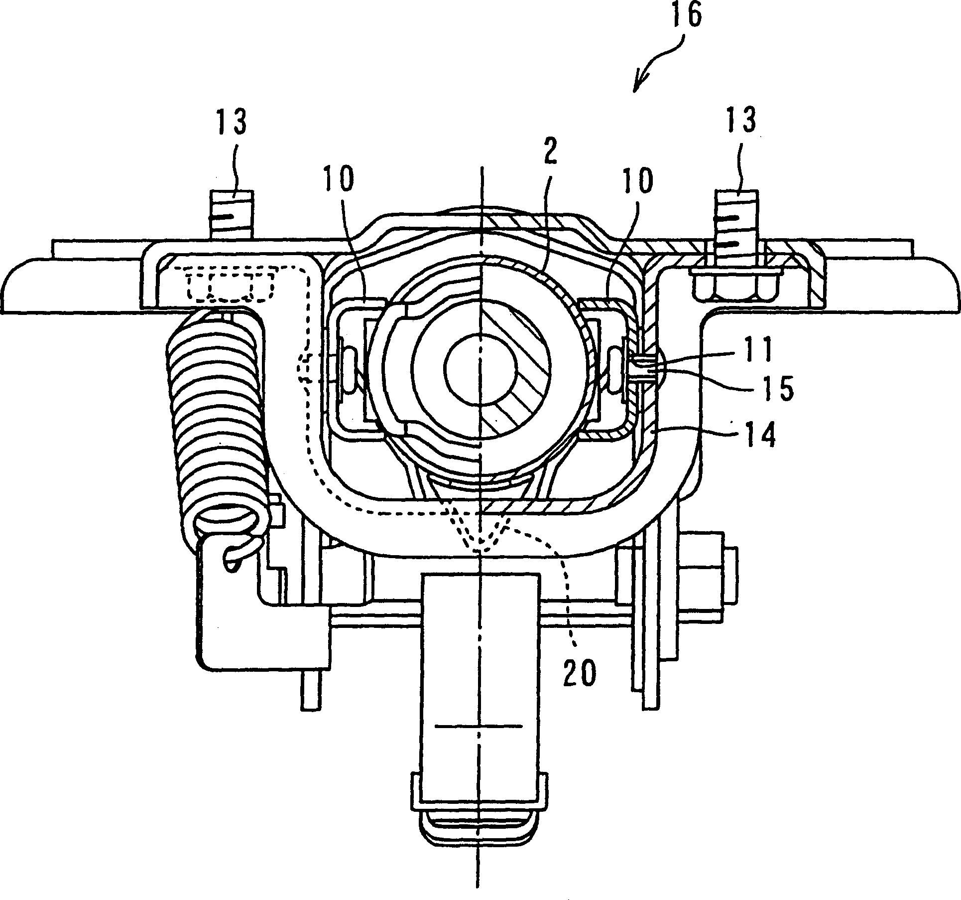
[0016] And, if Figure 1A and 2 As shown in 4, the inclined plate 10 is welded on both sides of the front end of the steering column 2 respectively. Each slant plate 10 is formed with a hole 11 and a slot 12 extending continuously from the hole 11 in substantially the same direction as the axial direction ...


PUM


Abstract

There is provided a steering column supporting apparatus in which tilt pins are locked on a tilt bracket fixed to a vehicle body and engaged with tilt plates welded to respective both sides of a steering column, and slotted holes extended in the axial direction of the steering column are formed in the tilt plates. A bulging part is formed on a lower surface of the steering column, and is designed to be larger in size than a gap between the lower surface of the steering column and the tilt bracket and increased in height as it goes rearward in the direction of the length of a vehicle. Therefore, it is possible to effectively reduce impact load applied to the steering column in the event of head-on vehicle crash.

Description

[0001] Cross References to Related Applications [0002] This application refers to the subject matter of Patent Application No. 2003-137616 filed in Japan on May 15, 2003, from which the present application claims priority. technical field [0003] The present invention relates to a steering column in which a vehicle steering shaft is disposed; and more particularly, the present invention relates to a support device for a tilting steering column capable of absorbing a shock applied in a head-on collision of a vehicle. Background technique [0004] Generally, as a support structure for a tilt steering column of a vehicle, a support structure disclosed in Japanese Patent Laid-Open No. 11-115770 and Japanese Utility Model Publication No. 62-23771 is known. [0005] The support structure disclosed in Japanese Patent Laid-Open No. Hei 11-115770 has a problem that the steering column cannot absorb energy when the steering column is released forward from the vehicle body in the ve...

Claims


Application Information

Patent Timeline
Patent Type & Authority Applications(China)
IPC IPC(8): B62D1/187B62D1/189B62D1/19
CPCB62D1/195B62D1/189
Inventor 冈本英明大枝敏文田中清司
Owner MITSUBISHI MOTORS CORP
Why Eureka
Try Eureka