Safety steering column, motor vehicle with a safety system and safety method

a safety system and steering column technology, applied in the direction of steering controls, vehicle safety arrangments, steering controls, etc., can solve the problems of unfavorable driver protection and desired function, and achieve the effect of reducing the risk of injury by an impact on the steering wheel and increasing the safety of passengers

Inactive Publication Date: 2006-11-02
THYSSENKRUPP PRESTA AG
View PDF7 Cites 60 Cited by
  • Summary
  • Abstract
  • Description
  • Claims
  • Application Information

AI Technical Summary

Benefits of technology

[0006] The object of the invention is provide for an increase in the passengers' safety in the event of such an accident. According to the present invention, this is accomplished by the provision of a novel safety steering column that includes a pyrotechnically driven steering column retraction means, triggerable in dependence on an accident condition. Thereby the steering wheel can be reliably moved away from the driver whereby his risk of injury by an impact on the steering wheel is significantly reduced.
[0020] 5. Safety steering column further developed in that the steering column retraction means can be controlled, especially, switched on and off in dependence on the driver's data.

Problems solved by technology

In dependence on the specific situation of an accident, a desired function and a protection of the driver are not reliably guaranteed.

Method used


Image

  • Safety steering column, motor vehicle with a safety system and safety method
  • Safety steering column, motor vehicle with a safety system and safety method
  • Safety steering column, motor vehicle with a safety system and safety method

Examples


first embodiment

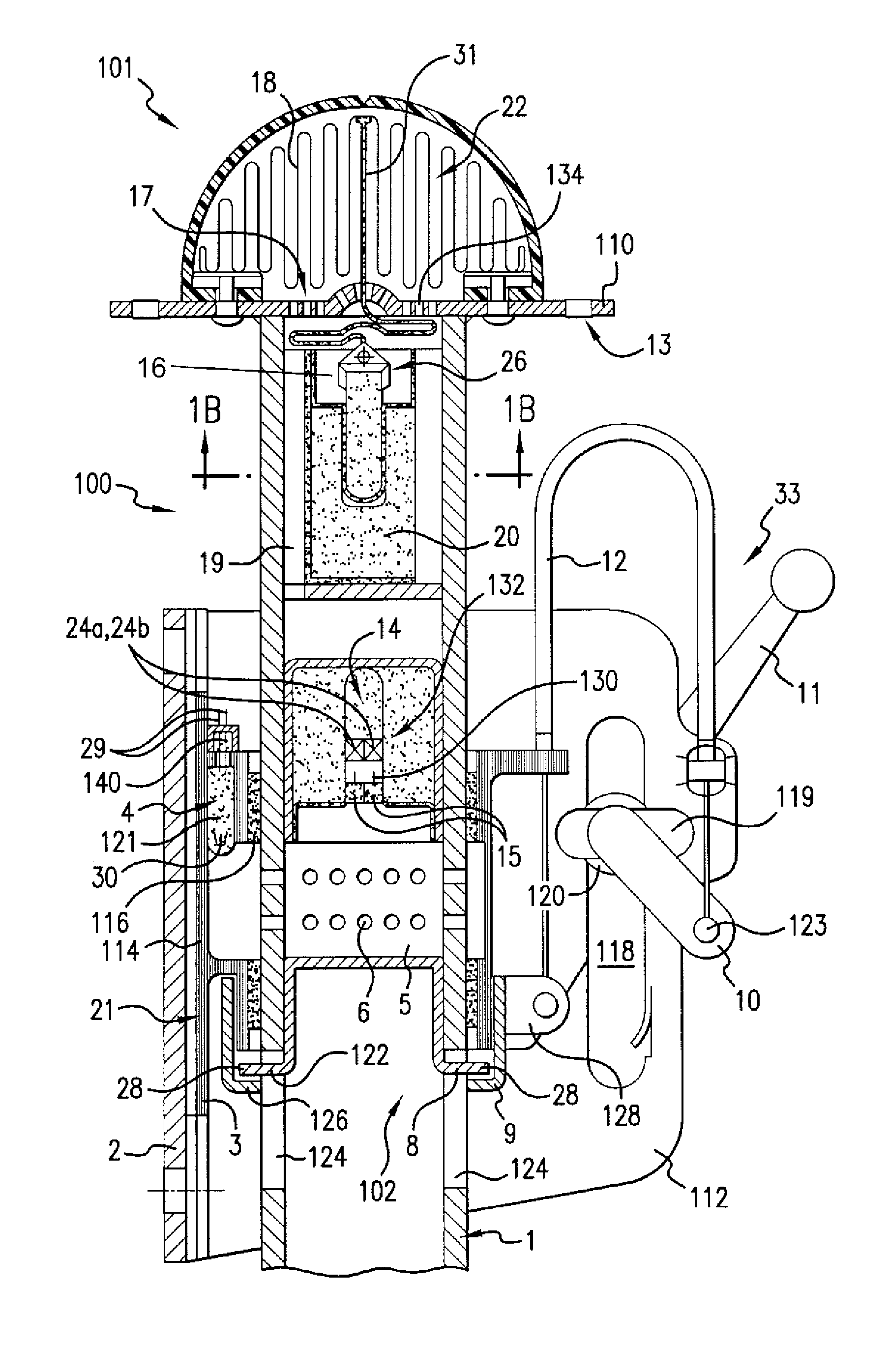
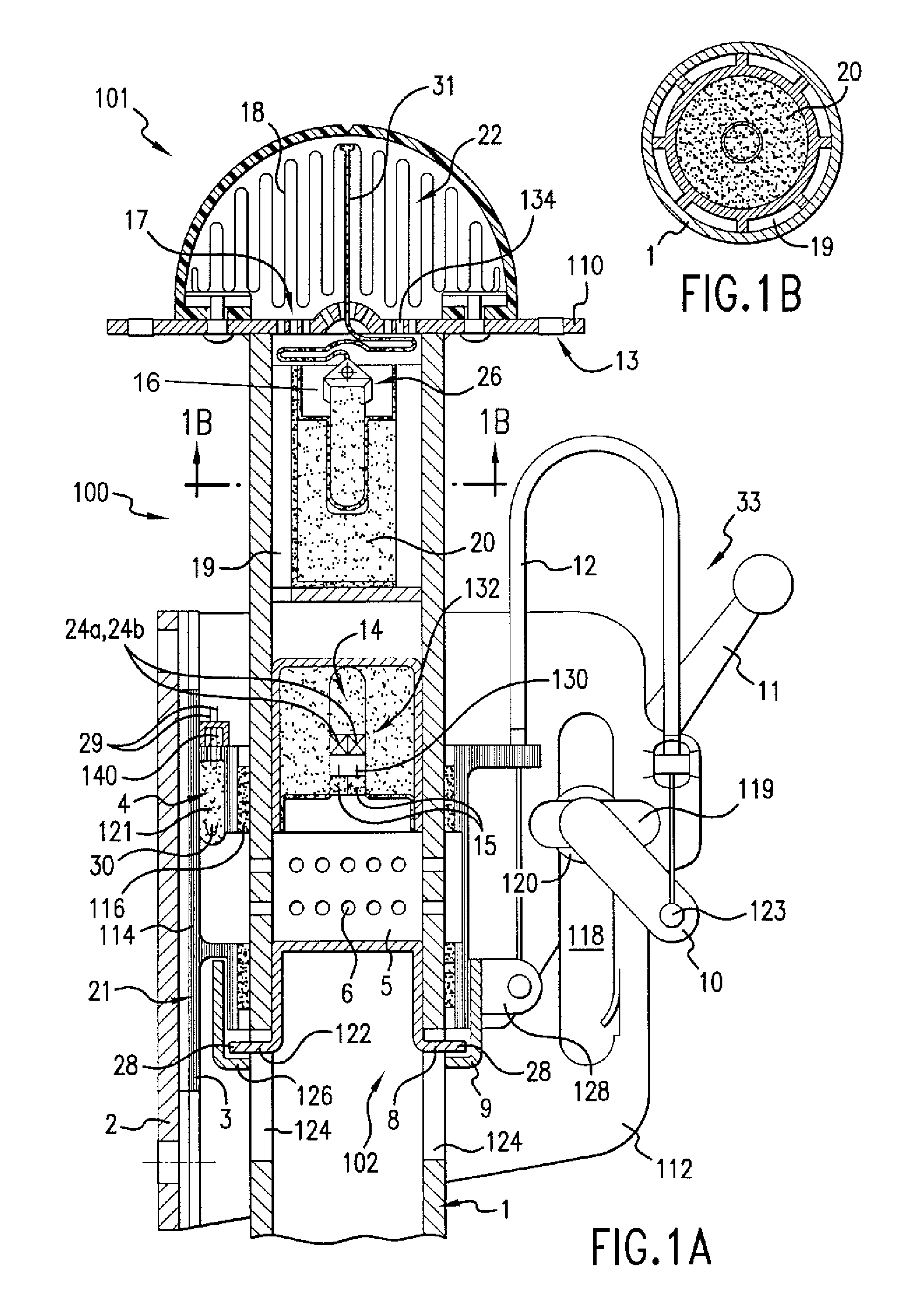
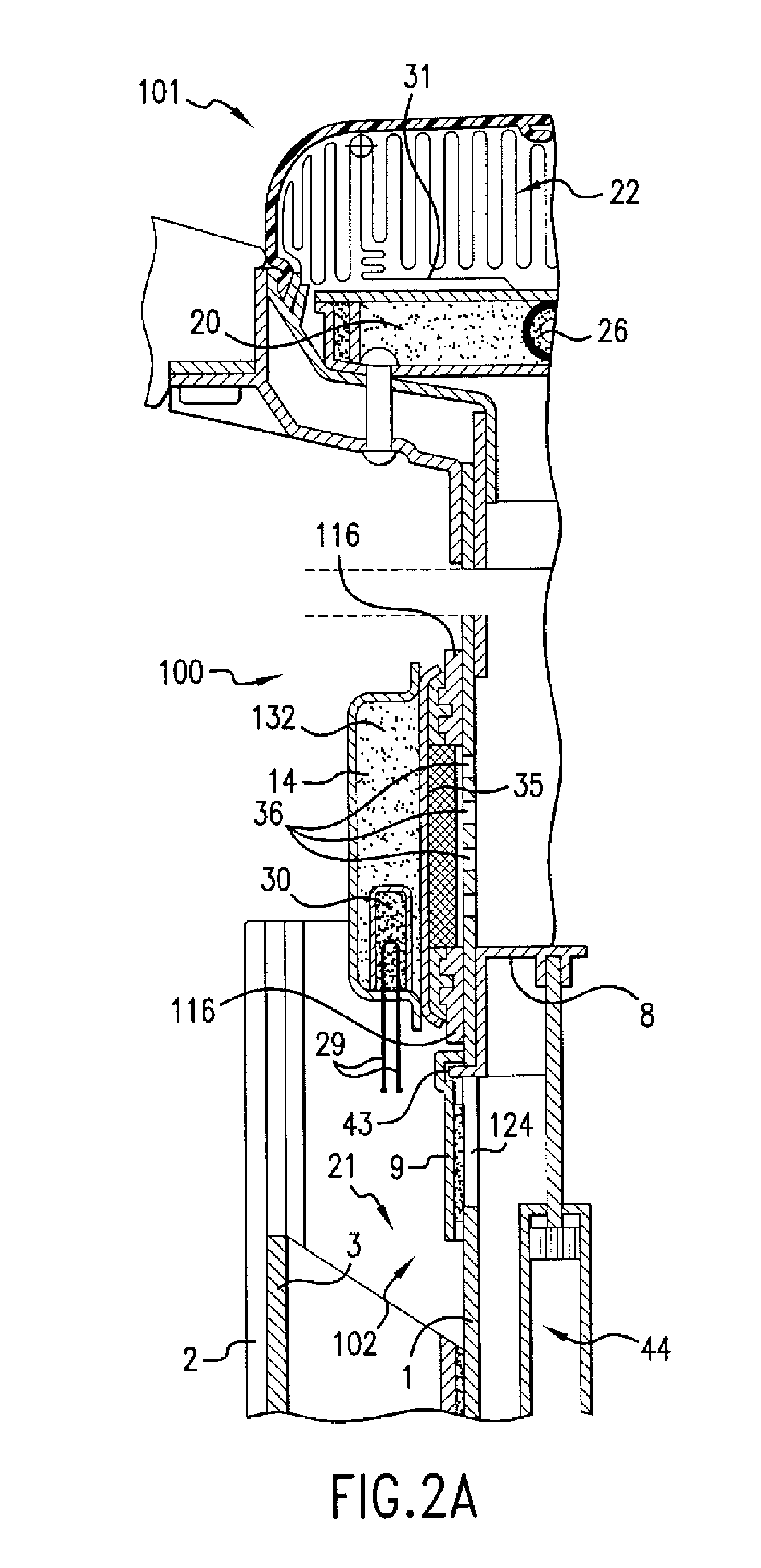
[0058] Referring now to the figures of the drawing, FIGS. 1A and 1B show the safety steering column of the invention. As shown, a safety steering column 100 with safety means or a safety system 101 in the form of steering column retraction means 102 and a driver airbag 22 which is two-staged, is shown in FIGS. 1A and 1B. The steering column 1 is angularly mounted in a motor vehicle in conventional fashion. As shown in FIG. 1A, the lower end of steering column 1 is directed toward the floor of the vehicle and angled to the front, while a steering wheel, not shown, is mounted to plate 110 fixed to the top of the steering column via bolt openings 13. The steering column 1 is rotatably mounted in and carried by the central cylindrical section 114 of a positioning carriage 3, which in turn, is slidably mounted on a mounting plate 2 that is fixed to the motor vehicle frame, directly or indirectly. The steering column 1 moves axially with the carriage 3, but can rotate relative to the carr...

sixth embodiment

[0136] In the scope of the sixth embodiment, in summary, by means of sitting position detection and / or fasten seat-belt detection, it can be decided or predetermined for the steering, long before an accident, if [0137] 1. the crash carriage is used for absorbing energy or as a moving carriage for a larger distance between head and bag, [0138] 2. the comfort longitudinal and / or vertical positioning is or is not opened in dependence of, for example, the person's weight or his seat-belt condition, [0139] 3. the airbag pressure opens the comfort positioning of the steering, and then, for example, by a pressure vessel, opens the airbag cover in any case so that the bag can softly come out.

[0140] Then the second stage of the airbag device can be triggered by the airbag, control device or alternatively by the same signal just like the first stage. This especially makes sense in the case of tall, heavy people who wear a seat-belt. In the case of small people not wearing a seat-belt, the ba...


PUM


Abstract

A safety steering column which is adjustable in its axial direction whereby pyrotechnically driven steering column retraction is provided for a positioning of a safety steering column in its axial direction, to move it away from the driver in case of an accident. Furthermore, a safety system incorporating such a safety steering column and a motor vehicle so equipped that can distinguish between different drivers regarding weight, size and belted condition; the system providing alternative safety measures depending on the driver's needs for protection.

Description

RELATED APPLICATION [0001] This application is a divisional of application Ser. No. 10 / 459,413 filed on Jun. 10, 2003, which is a continuation-in-part of application Ser. No. 09 / 700,274 filed Jan. 25, 2001, now abandoned, the contents of which are here incorporated by reference in their entirety.BACKGROUND OF THE INVENTION [0002] 1. Field of Invention [0003] The invention relates to a safety steering column, a motor vehicle with a safety system and a safety method. [0004] 2. Prior Art [0005] In practice, safety steering columns are known which in case of a front impact or crash of a motor vehicle equipped with a known safety steering column, a movement of the steering wheel away from the driver will be generated. In these constructions mere mechanical systems are involved which use only the kinetic energy of the motor vehicle for steering column positioning. In dependence on the specific situation of an accident, a desired function and a protection of the driver are not reliably gua...

Claims


Application Information

Patent Timeline
Patent Type & Authority Applications(United States)
IPC IPC(8): B62D1/00B60R21/203B60R21/16B60R21/20B60R21/215B60R21/217B60R21/233B60R21/26B60R21/264B62D1/19
CPCB60R21/203B60R21/2032B60R21/2035B60R21/217B62D1/197B60R2021/23382B60R2021/26035B60R2021/2633B60R2021/2648B60R21/2338
Inventor MULLER, OLAF
Owner THYSSENKRUPP PRESTA AG
Why Eureka
Try Eureka