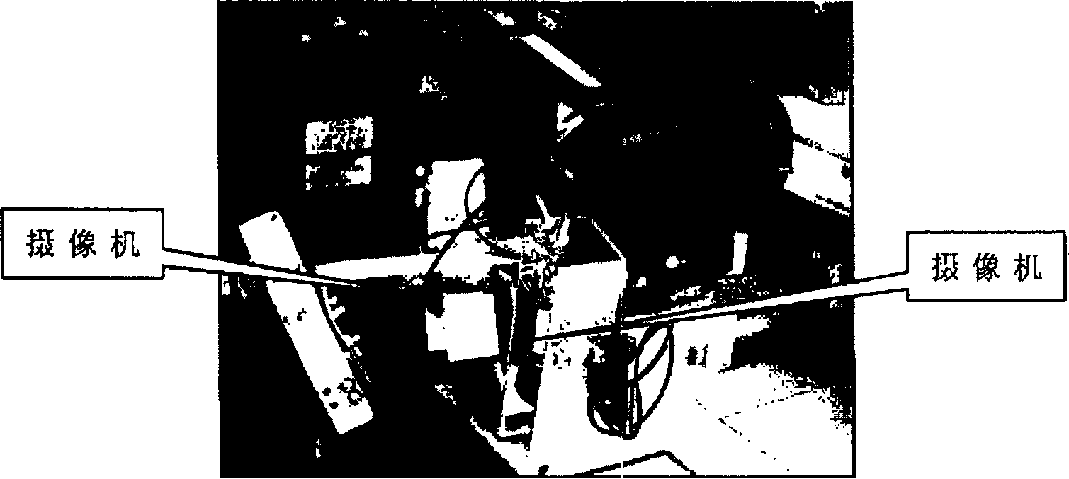
Pickup camera self calibration method based on robot motion
A technology of robot movement and camera, applied in the direction of manipulators, manufacturing tools, etc., can solve the problems of camera movement limitation and strictness, and achieve the effect of meeting the needs of visual measurement
Inactive Publication Date: 2005-03-09
INST OF AUTOMATION CHINESE ACAD OF SCI
View PDF0 Cites 15 Cited by
- Summary
- Abstract
- Description
- Claims
- Application Information
AI Technical Summary
Problems solved by technology
[0003] The defect of the current camera self-calibration technology is that the restrictions on camera movement are relatively strict
Method used
View moreImage
Smart ImageViewing Examples
Examples
Embodiment 1
[0035] The camera calibrated in Example 1 has been applied to the seam tracking of the arc welding robot. The camera calibrated in Example 2 has been applied to the positioning and navigation of mobile robots.
Login to View More PUM
 Abstract
A self-calibrating method based on the movement of robot for the camera installed to terminal end of robot includes choosing a point ni the visual field of camera as a characteristic origin point, arbitrarily moving the terminal end of robot several times without changing its posture to obtain more characteristic origin points, using the least square method to obtain the internal and external parameters of camera, changing its postures, obtaining several space straight line from the center of optical axis and the imaging dots on image plane, using their intersection point to calibrate the position of characteristic point in basic coordinate system, and calculating the external parameter of terminal end.
Description
technical field [0001] The invention relates to a camera calibration technology in the field of robot vision control, in particular to a method for obtaining internal and external parameters of a camera. technical background [0002] Traditionally, the camera is calibrated by using the calibration reference object-target. Specifically, a calibration reference object of known shape and size is placed in front of the camera, and the internal and external parameters of the camera are calculated by measuring the imaging position of the reference object on the image plane. . In practical applications, it is not allowed to place a specific calibration reference object in the environment in many cases. Therefore, the camera calibration technology (ie, self-calibration technology) that does not require a specific calibration reference object has received more and more attention. This technology is used in robots. It has broad application prospects in hand-eye system and head-hand s...
Claims
Login to View More Application Information
Patent Timeline
 Patent Type & Authority Applications(China)
IPC IPC(8): B25J13/08
Inventor 徐德谭民
Owner INST OF AUTOMATION CHINESE ACAD OF SCI
Features
- R&D
- Intellectual Property
- Life Sciences
- Materials
- Tech Scout
- Unparalleled Data Quality
- Higher Quality Content
- 60% Fewer Hallucinations
Learn More Browse by: Latest US Patents, China's latest patents, Technical Efficacy Thesaurus, Application Domain, Technology Topic, Popular Technical Reports.
© 2025 PatSnap. All rights reserved.Legal|Privacy policy|Modern Slavery Act Transparency Statement|Sitemap|About US| Contact US: help@patsnap.com


