Method for making optical fiber preform having ultimately low PMD through improvement of ovality

An optical fiber preform and preform technology, which can be used in manufacturing tools, glass manufacturing equipment, optics, etc., can solve problems such as volatilization limitation, and achieve the effect of improving ellipticity and PMD.

An optical fiber preform and preform technology, which can be used in manufacturing tools, glass manufacturing equipment, optics, etc., can solve problems such as volatilization limitation, and achieve the effect of improving ellipticity and PMD.

CN1592860AInactive Publication Date: 2005-03-09LG CABLE INC

Image

  • Method for making optical fiber preform having ultimately low PMD through improvement of ovality
  • Method for making optical fiber preform having ultimately low PMD through improvement of ovality
  • Method for making optical fiber preform having ultimately low PMD through improvement of ovality

Examples


Embodiment Construction

[0033] Hereinafter, preferred embodiments of the present invention will be described in detail with reference to the accompanying drawings.

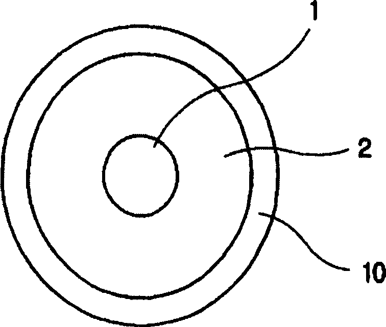
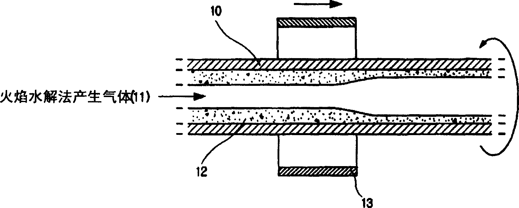
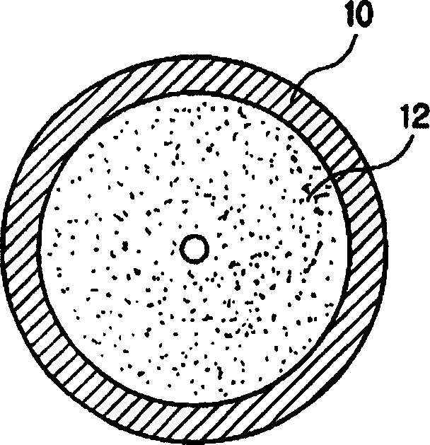
[0034] first, figure 2 It is a bottom sectional view for explaining a process of forming a flame hydrolysis gas-generated deposit on the inner wall of a hollow preform as a pretreatment for shrinkage according to the present invention. refer to figure 2 , when a tube 10 made of, for example, quartz glass is rotated in the circumferential direction at a constant speed, the flame hydrolysis produces a gas 11 such as SiCl 4 、GeCl 4 and POCl 3 Injected into the tubing 10 together with oxygen. Then, by moving the torch 13 having a semi-cylindrical shape in the longitudinal direction of the tube 10 , the tube 10 is heated so that a transparent glass layer is deposited on the inner wall of the tube 10 . At this point, the concentration of the flame hydrolysis gas 11 is controlled to adjust the refractive index of the deposited layer whil...


PUM


Abstract

A method for making an optical fiber preform having an ultimately low PMD (Polarization Mode Dispersion) through improvement of ovality is provided. This method has several collapse steps for collapsing an optical fiber preform having a clad / core deposition layer formed in a preform tube in which a rate of collapse is 0.01-0.06 mm / min at each collapsing step. By using this method, ovality and PMD of the optical fiber preform may be improved.

Description

technical field [0001] The present invention relates to a kind of method that finally has the optical fiber preform rod (perform) of low PMD (polarization mode dispersion) by the improvement of optical fiber ellipticity, and particularly relates to a kind of shrinking rod (collapse) rate that is relevant to temperature by optimizing, blowtorch The method of improving the ellipticity and PMD of the optical fiber by the moving speed of the moving speed and the difference between the internal pressure and the external pressure of the hollow preform during the shrinkage process. [0002] Furthermore, the present invention relates to a method for improving PMD by keeping the inner diameter of the hollow preform at a fixed value in the range of 2 mm to 4 mm before closing the hollow preform through several shrinkage treatments, and then sealing together using etching Hollow preforms to minimize dips. Background technique [0003] In general, an optical fiber widely used as a wave...

Claims


Application Information

Patent Timeline
09 Mar 2005
Publication
CN1592860A
IPC
C03B37/018
CPC
C03B37/01869; C03B37/01861; Y02P40/57
Inventors
姜秉润; 文俊皓