
An Unclear Root Welding Process for Wind Turbine Tower Tube Sections

A welding process, fan tower technology, applied in welding equipment, welding equipment, welding accessories and other directions, can solve the problems of difficult assembly, low welding efficiency, poor assembly accuracy, etc., to ensure welding quality and welding efficiency, Avoid internal stress concentration and achieve the effect of supporting and pressing force

Active Publication Date: 2021-11-26
NANTONG BLUE ISLAND OFFSHORE CO LTD
View PDF5 Cites 0 Cited by
  • Summary
  • Abstract
  • Description
  • Claims
  • Application Information

AI Technical Summary

Problems solved by technology

[0003] The traditional multi-layer welded circular seam welding method has the following defects: 1. The assembly before spot welding is extremely difficult and the accuracy of the assembly is poor. The stress concentration of adjacent barrel sections at the ring seam, the internal stress of the welded tower section at the welded joint position is large, which affects the structural strength of the fan tower; It is still an irregular elliptical shape. During the submerged arc welding process, with the rotation of the roller, the distance between the welding torch that maintains a fixed position and the circular seam varies from time to time, and the deviation is large, which affects the welding quality. 3. Due to The quality of bottoming welding is poor, and it is necessary to use carbon arc gouging to weld the inner and outer grooves, otherwise the quality cannot be guaranteed, and multi-layer welding is performed, the welding workload is huge, the welding efficiency is low, and carbon arc gouging There is lake light radiation in Qinggen, the noise generated and the formed carbon residue and scale pollute the surrounding environment

Method used


Image

  • An Unclear Root Welding Process for Wind Turbine Tower Tube Sections
  • An Unclear Root Welding Process for Wind Turbine Tower Tube Sections
  • An Unclear Root Welding Process for Wind Turbine Tower Tube Sections

Examples


Embodiment Construction

[0035] In order to deepen the understanding of the present invention, the present invention will be further described below in conjunction with the embodiments and accompanying drawings. The embodiments are only used to explain the present invention, and do not constitute a limitation to the protection scope of the present invention.

[0036] In this embodiment, an unclear root welding process for wind turbine tower tube joints, the specific steps include:

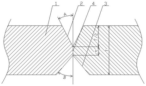
[0037] S1. Beveling of ring seam of cylinder section 1: asfigure 1 As shown, the angle A of the inner groove 2 is 25°-30°, the angle B of the outer groove 3 is 35°-40°, and the barrel section 1 has a blunt edge t that facilitates the pairing of two adjacent barrel sections 1. -4mm;

[0038] S2. Position the ellipticity adjustment device: place the two cylinder sections 1 on the corresponding roller tire frame 5, and position the ellipticity adjustment devices on the two cylinder sections 1 respectively. The circular mecha...


PUM


Abstract

The invention relates to an unclear root welding process for a fan tower tube section. The specific steps include: S1, groove opening of the ring seam of the tube section; S2, a positioning ovality adjusting device; S3, grouping two adjacent tube sections ; S4, inner groove welding; S5, outer groove welding; S6, remove the outer locking mechanism. The invention has the following advantages: before the grouping, the ovality adjusting device is used to complete the rounding treatment of the two cylinder sections, so as to improve the accuracy of the grouping, at the same time, the welding quality is ensured, the operation steps of the spot welding of the grouping are omitted, and the internal stress concentration is avoided. Improve overall weld strength.

Description

Technical field: [0001] The invention relates to the field of welding of wind turbine tower barrel joints, in particular to an unclear root welding process for wind turbine tower barrel joints. Background technique: [0002] The wind turbine tower generally consists of 3-5 tower sections, and each section is formed by butt welding of multiple tube sections. The main welds include longitudinal seams and circular seams. Each tube section is 2-4 meters in length and about 4 The -8m steel pipes are butt-welded to form the tower section. At present, the welding steps of the adjacent tube sections are as follows: due to the large diameter of the tube section, they are placed on the roller frame before the pairing. Due to their own gravity, the adjacent two pairs The cylinder joints are irregular elliptical shapes, so it is very difficult to assemble the cylinder joints. Before welding, the outer grooves of the two adjacent cylinder joints need to be preliminarily positioned for sp...

Claims


Application Information

Patent Timeline
Patent Type & Authority Patents(China)
IPC IPC(8): B23K9/18B23K9/32B23K33/00B23K37/053B23K9/00
CPCB23K9/18B23K9/32B23K33/00B23K37/053B23K9/0026B23K37/0538
Inventor 那雪冬
Owner NANTONG BLUE ISLAND OFFSHORE CO LTD
Learn More