Electrical ionizer

A technology of ionizers and ions, applied in the field of ionizers, can solve problems such as cost and control circuit generation

Inactive Publication Date: 2005-03-30
MEECH STATIC ELIMINATORS LTD
View PDF5 Cites 2 Cited by
  • Summary
  • Abstract
  • Description
  • Claims
  • Application Information

AI Technical Summary

Problems solved by technology

This has some benefits for ion balance, but presents problems with control circuitry and additional cost in the overall assembly to achieve balance

Method used


Image

  • Electrical ionizer
  • Electrical ionizer
  • Electrical ionizer

Examples


Embodiment Construction

[0028] best practice

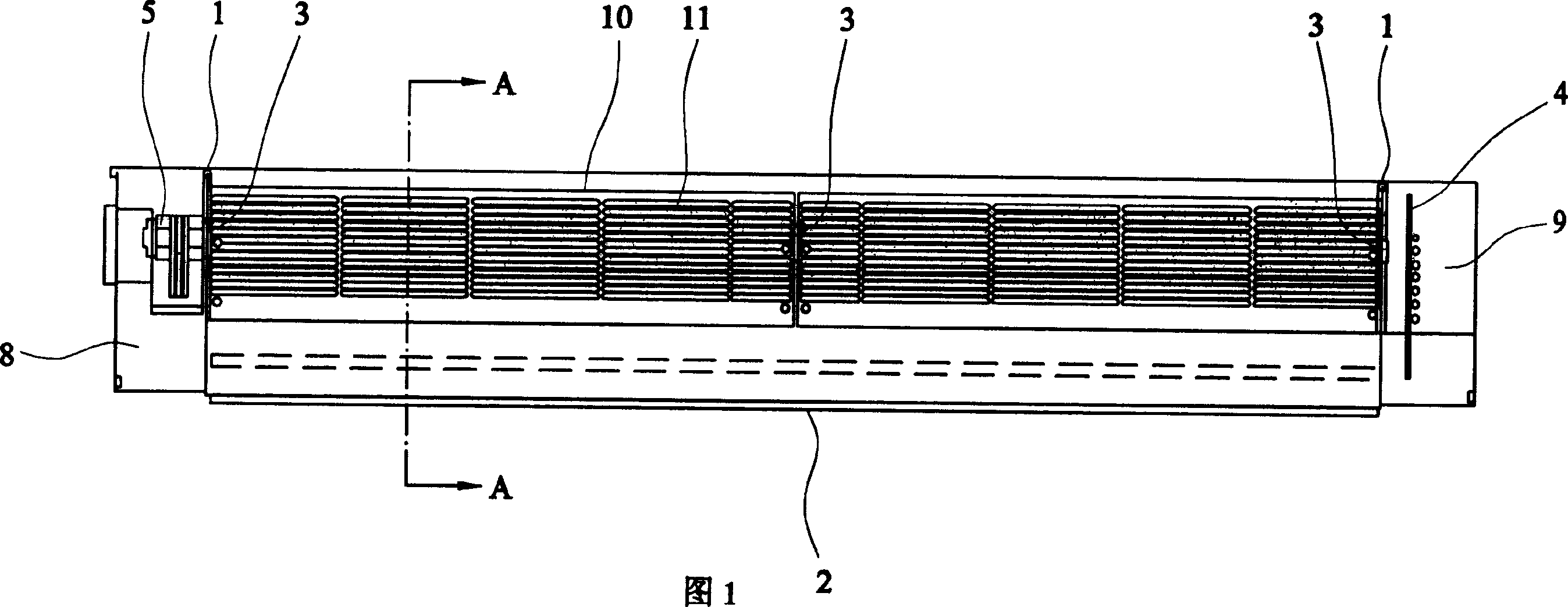
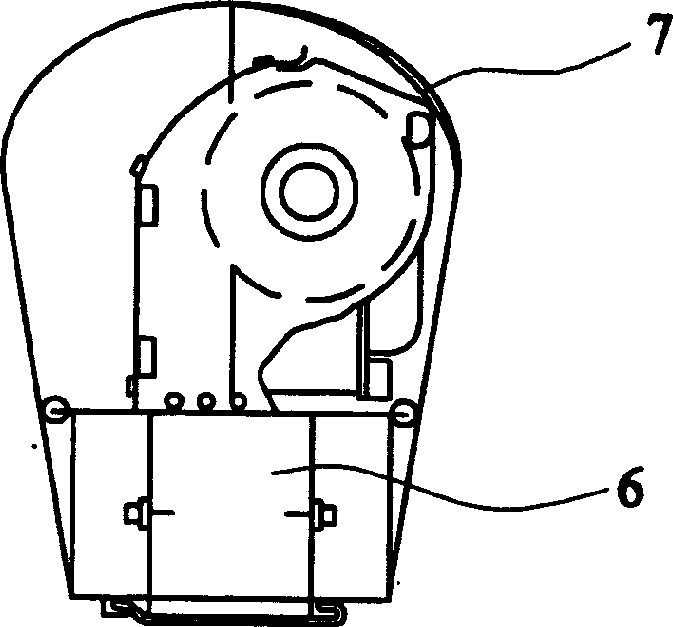
[0029] Figures 1 and 2 illustrate an ionizer suitable for use in a cleanroom environment in accordance with one embodiment of the present invention. The ionizer comprises: a cross-flow fan with an impeller 10 driven by an impeller motor 5 and housed in a casing 7 . The housing is made of stainless steel (other materials suitable for cleanroom environments are also available) and has a "teardrop" profile (such as figure 2 shown). This shape positions the ionizer in the laminar downdraft airflow impinging in the clean room without unduly disturbing the airflow.

[0030] Air enters the unit through inlet 11 and exits through outlet 12 . A partition 1 is provided on each end of the unit and is sealed to the housing 7 by means of a gasket in order to confine the air flow to the desired part of the unit. The partition 1 also prevents particulate contamination generated by the motor 5 and associated control electronics from entering the air stream.

[0031...


PUM


Abstract

An electrical ionizer comprising a fan (5) for producing a laminar flow of air; a positive ion emitter (6b) for ejecting positive ions into the flow of air; a negative ion emitter (6a) for ejecting negative ions into the flow of air; a positive voltage supply (27) to the positive ion emitter; a negative voltage supply (28) to the negative ion emitter; and a microprocessor (30) for controlling the positive and negative voltages to obtain a desired ion balance in the flow of air. The fan (5) is a crossflow fan, resulting in a highly uniform and laminar beam of air along the entire length of the fan, with reduced gaps in the air flow and consistent velocity of air, improving ion balance. The use of a crossflow fan also enables the operating mechanism to be contained within a simple 'teardrop' profile, and for operative parts of the device, for example the motor, the bearings, and electronics such as printed circuit boards to be housed outside the air flow, thereby eliminating a possible source of contamination of the air flow. For a comparable size of ionizer enclosure, approximately twice the mass flow, at higher velocities, can be generated as a similar conventional device using axial fans, and at reduced noise levels.

Description

technical field [0001] This invention relates to electrical ionisers, and more particularly to ionisers used in "clean rooms" for sensitive electronic equipment components (such as semiconductor equipment, computer components, hard disks, LCDs, etc.). Background technique [0002] Ionizers are commonly used in environments where ions are generated in the air and thereby neutralize surface charges. In most applications, the static charge is reduced to a few hundred volts, which is nominally sufficient to eliminate dust pickup. However, in the electronics industry, especially in clean rooms, electrostatic charges of several hundred volts have a devastating effect on semiconductor devices such as microprocessor chips. In these cases, it is important to ensure that the ionization delivered by the neutralization system is balanced and specifically targeted to the area requiring neutralization. In many applications, static charge growth must be limited to a few volts, possibly +...

Claims


Application Information

Patent Timeline
Patent Type & Authority Applications(China)
IPC IPC(8): H01T23/00
CPCH01T23/00
Inventor 克里斯托弗·弗朗西斯西蒙·哈彻戴维·罗杰斯戴维·斯蒂芬斯
Owner MEECH STATIC ELIMINATORS LTD
Why Eureka
Try Eureka